background image


REMOVAL, SHARPENING AND RE-INSTALLATION OF CHIPPER KNIFE 


HOW TO REMOVE THE KNIFE 

• 

Stop the engine. 

• 

Remove both spark plug wires and keep away from spark plugs. 

• 

Disconnect battery at negative terminal. 

• 

Remove both access covers from the chipper basic machine. 

• 

Rotate the chipper disk until the three countersunk screws and nylock nuts attaching the 
knife to the flywheel are visible through the access doors. 

• 

Clean out the heads of the allen screws with an awl or sharp tool. 

• 

Insert a 3/16” allen wrench into the heads of the screws. 

• 

Use a ½” socket and ratchet to remove the nylock nuts from the screws. 

• 

Remove all three allen screws and nuts in this manner. 


KNIFE SHARPENING 

• 

You should never attempt to sharpen the chipper knife (or knives) freehand. 

• 

It is extremely important that the 45 degree angle be maintained consistently for proper 
performance. 

• 

The chipper knife should be taken to a machine shop for proper sharpening. 

• 

Excessive heat generated during the sharpening process will damage knives and weaken 
the metal.  

Be sure the knife is not overheated.


KNIFE INFORMATION 

• 

The chipper knife should be checked routinely for sharpness. 

• 

Using a dull knife will decrease performance and cause excessive vibration that will 
cause damage to the chipper. 

• 

How many times a knife can be sharpened is determined by how much material needs to 
be taken off to sharpen or to compensate for dents or gouges. 

• 

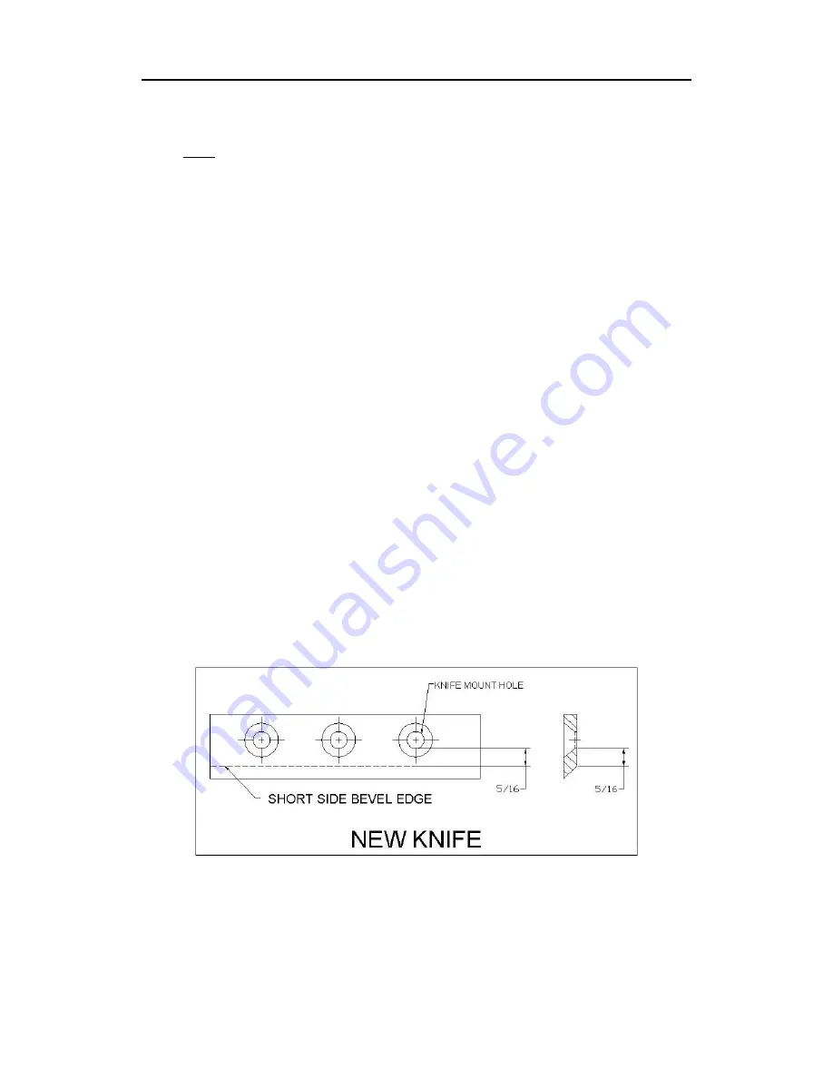
A new chipper knife has 5/16” measurement between the short side bevel edge and the 
knife mounting holes.  See figure 2. 


Figure 2 


22

Summary of Contents for TLC18-CHP

Page 1: ...CHP This manual contains information concerning proper and improper operating procedures warnings maintenance troubleshooting assembly and tips Everyone who operates this machine should read these ins...

Page 2: ...DED USE NEVER USE YOUR CHIPPER FOR ANY OTHER PURPOSE THAN CHIPPING LIMBS IT IS DESIGNED FOR THIS USE AND ANY OTHER USE MAY CAUSE SERIOUS INJURY DANGER Rotating cutting blade Keep hands and feet out of...

Page 3: ...from this product contains chemicals known to the state of ects or other reproductive harm MAKE CERTAIN THAT ALL SAFETY LABELS ON THIS EQUIPMENT ARE KEPT CLEAN AND IN GOOD CONDITION IF YOU NEED REPLA...

Page 4: ...091 0057 091 0059 091 0062 091 0088 091 0093 4...

Page 5: ...091 0256 091 0378 091 0379 091 0380 091 0381 5...

Page 6: ...091 0384 913 0265 6...

Page 7: ...lasses or goggles during operation and while performing any adjustment or repair to protect eyes from foreign objects that may be thrown from the machine Be sure your glasses or goggles fit properly A...

Page 8: ...and safety devices in place and operating properly Do not operate the machine if all safety guards are not in place Do not use the unit with the chipper hopper removed The muffler and engine become ho...

Page 9: ...roper position These safety devices are for your protection Never store machine with fuel in the fuel tank inside a building where ignition sources are present such as hot water and space heaters clot...

Page 10: ...FUTURE REFERENCE HAZARD This unit is equipped with an internal combustion engine and should not be used on or near any unimproved forest covered brush covered or grass covered land unless the engine...

Page 11: ...GAUGE 3 EA 3 8 USS FLATWASHER 1EA LOCKING KNOB TOOLS REQUIRED FOR ASSEMBLY REGULAR BOX WRENCH SOCKET AND SOCKET DRIVER STEP I UNPACKING AND CHECKING CONTENTS 1 Remove all items from the crate 2 After...

Page 12: ...he hitch assembly and secure with the hair cotter pin item 50 pg 30 STEP IV ATTACHING THE DISCHARGE CHUTE 1 Loosen the two 5 16 18 x 4 bolts on the chipper enough that the mounting plates on the disch...

Page 13: ...nd secure with the locking knob 4 DO NOT RUN MACHINE WHILE MAKING THIS ADJUSTMENT PLEASE DISCONNECT THE SPARK PLUG BEFORE CONTINUING To change the side to side direction of the flow simply loosen the...

Page 14: ...the back of the light Push the brown wire into the top right hole 4 On the curb side light put the green wire through the access hole and into the top left hole on the back of the light Push the brow...

Page 15: ...E STARTING Oil and Gas Fill Up Oil Capacity 1 quarts 48 ounces Fuel Capacity 9 quarts OIL Use a high quality detergent oil classified For Service SF SG SH SJ or higher Do not use special additives Cho...

Page 16: ...gum from forming in the fuel system or on essential carburetor parts Purchase fuel in quantity that can be used within 30 days Do not use gasoline which contains Methanol Do not mix oil with gasoline...

Page 17: ...each choke adjustment TO STOP ENGINE Move throttle to SLOW Turn key to OFF Remove key and store out of reach of children Close fuel shut off valve Operation Notes At engine start up the engine of your...

Page 18: ...ind can also change discharge direction so be aware Always keep hands out of the chipper hopper Never operate the chipper without the chipper hopper in place Do not transport the chipper while the eng...

Page 19: ...ORTANT THAT YOU IMMEDIATELY SHUT OFF THE MACHINE IF IT BECOMES JAMMED ONLY YOUR OPERATOR EXPERIENCE WILL TELL YOU HOW FAST TO FEED LIMBS CHECK TO SEE THAT THE FLYWHEEL WILL TURN FREELY BEFORE YOU STAR...

Page 20: ...t in the chipping chamber Reinstall discharge chute weldment Be sure to install the discharge chute so that it engages the safety switch properly allowing the machine to be restarted NOTE The machine...

Page 21: ...TO SERVICE THE ENGINE BEFORE YOU START IT 4 When the steel chipping knife item 11 pg 33 needs replacing or sharpening refer to the section on removal sharpening and re installation 5 Care must be exe...

Page 22: ...ARPENING You should never attempt to sharpen the chipper knife or knives freehand It is extremely important that the 45 degree angle be maintained consistently for proper performance The chipper knife...

Page 23: ...tighten the knife to the chipper disk with bolts and nylock locking nuts If you are installing a new knife use the new hardware that comes with the knife when attaching it to the chipper disk Tighten...

Page 24: ...pped with an oil drain valve to make changing the oil easy The valve is located on the engine on the towing side of the machine Place engine level Disconnect spark plug wires and keep it away from spa...

Page 25: ...1 pg 29 by placing a straightedge across both faces as shown in figure 2 If adjustment is necessary correct alignment by moving rotor pulley in or out on the rotor shaft Do not make adjustment by movi...

Page 26: ...Check for loose or missing belt tighten When chipping log seems to vibrate excessively hammers hands The knife is dull Gap between knife wear plate is too great Remove knife sharpen be sure to maintai...

Page 27: ...y multi purpose lithium grease 40 HOURS Change engine oil Check tire pressure Remove and sharpen or replace chipper knife Sharpen wear plate Per recommendations Do not overfill Add or adjust as requir...

Page 28: ...replace all springs DISASSEMBLY OF EXISTING CLUTCH 1 Remove retainer ring and press off drum assembly 2 Release one hook end of spring from shoe pin Use tape wrapped pliers to avoid nicking spring 3 R...

Page 29: ...T BASIC MACHINE 17 090 0438 3 5 16 18 J NUT 18 030 0193 2 BELT 19 703 0424 2 1 4 SQ X 2 KEY 20 030 0237 1 BUSHING 21 030 0211 1 2 GROOVE SHEAVE 22 913 0328 1 Z BRACKET WLDMNT BELT GUARD 23 911 0214 1...

Page 30: ...BATTERY CABLE 50 500 0039 1 3 16 COTTER PIN 51 911 0035 1 STAND 52 911 0221 2 HITCH ARM MOUNT PLATE 53 913 0231 1 FRAME 54 911 0070 1 AXLE WELDMENT 55 913 0206 2 TAIL LIGHT MOUNT BRACKET 56 030 0265...

Page 31: ...31...

Page 32: ...32...

Page 33: ...42 3 5 16 18 X 1 FHSHCS 13 913 0271 1 CHIPPER DISK 14 913 0236 1 SCROLL WELDMENT 15 913 0279 1 CHIPPER SIDE PLATE WELDMENT 16 090 0470 3 20 NYLOCK LOCKNUT 17 090 0245 3 SAE FLATWASHER 18 090 0077 9 5...

Page 34: ...34...

Page 35: ...NOTES 35...

Page 36: ...NOTES COUNTRY HOME PRODUCTS Meigs Road P O Box 25 Vergennes Vermont 05491 1 800 DR OWNER 376 9637 12 31 03 36...

Reviews: