


29
l
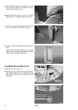
Hook upper edge of operator's panel into the slot
of the upper cover panel intended for this purpose
(fig. 23).
Fig. 24
l
Fix the control board with the screw (accessories
bag) at the vertical cover (fig. 24).
Fig. 23
l
Now remove both side trimmings from box no. 4
and assemble them to exhaust air unit (Fig. 26, 27,
28).
Fig. 26
Fig. 27
door
element
insert here
Fig. 25
l
Fix the cover plate (fig. 25), which is in box no. 4
and remove the protection film.
Pay attention to the position of the recess
area
control panel
vertical cover
english