


9
Power Connection
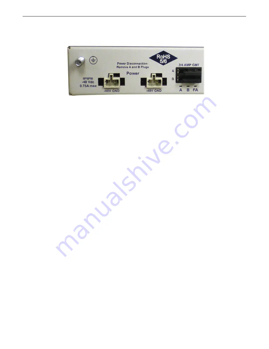
6.3
Power connectors and fuses
The NetGuardian has two screw terminal barrier plug power connectors, located on the left side of the back panel.
(See Figure 6.3.1.)
Before you connect a power supply to the NetGuardian, test the voltage of your power supply:
·
Connect the black common lead of a voltmeter to the ground terminal of the battery, and connect the red
lead of the voltmeter to the battery's –48 VDC terminal. The voltmeter should read
between –43 and –53
VDC
. If the reading is outside this range, test the power supply.
To connect the NetGuardian to a power supply, follow these steps:
1.
Remove Fuse A and Fuse B from the back panel of the NetGuardian.
Do not reinsert the fuse until all
connections to the unit have been made.
2.
Remove the power connector plug from Power Connector A. Note that the plug can be inserted into the
power connector only one way — this ensures that the barrier plug can only be reinserted with the correct
polarity. Note that the
–48V terminal is on the left
and the
GND terminal is on the right
.
3.
Use the grounding lug to properly ground the unit.
4.
Insert a
battery ground
into the power connector plug's
right terminal
and tighten the screw; then insert
a
–48 VDC
line to the plug's
left terminal
and tighten its screw.
5.
Push the power connector plug firmly back into the power connector. If the power feed is connected
correctly, the LED by the connector will light
GREEN
. The LED by the power connector will be off if the
power feed is reversed.
6.
Repeat Steps 2–5 for Power Connector B.
7.
Reinsert Fuse A and Fuse B to power the NetGuardian. The front panel LEDs will flash
RED
and
GREEN
.
Summary of Contents for NetGuardian 216F
Page 16: ...12 6 5 2 Discretes 1 16 Connector Pinout Diagram Pinout Diagram for Discretes 1 16 connector...
Page 54: ...50...
Page 55: ...51...
Page 59: ......


