


R E A S S E M B L Y H I N T S & T I P S
WIL-11140-E-03
17
WILDEN PUMP & ENGINEERING, LLC
ASSEMBLY:
Upon performing applicable maintenance to the air
distribution system, the pump can now be reassembled.
Please refer to the disassembly instructions for photos
and parts placement. To reassemble the pump, follow
the disassembly instructions in reverse order. The air
distribution system needs to be assembled fi rst, then
the diaphragms and fi nally the wetted path. Please fi nd
the applicable torque specifi cations on this page. The
following tips will assist in the assembly process.
•
Clean the inside of the center section shaft bushing
to ensure no damage is done to new shaft seals.
•
Remove the air chamber from the center block
assembly prior to removing the center block adapter
plate from the air chamber.
•
When reassembling the pump, leave wetted
path fasteners somewhat loose until all wetted
components are installed. This will simplify proper
wetted component joint alignment and will ensure
proper sealing.
•
Stainless steel bolts should be lubed to reduce the
possibility of seizing during tightening.
SHAFT SEAL INSTALLATION:
Pre-installation
•
Once all of the old seals have been removed, the
inside of the bushing should be cleaned to ensure
no debris is left that may cause premature damage
to the new seals.
T810 MAXIMUM TORQUE SPECIFICATIONS
Description of Part
Torque
Air Valve
9.0 N•m (80 in-lbs)
Center Block Assembly
27.1 N•m (20 ft-lbs)
Center Block Adapter Plate to Air Chamber
3.8 N•m (34 ft-lbs)
Outer Piston
4.5 N•m (40 ft-lbs)
Flap Valve Assembly
1.7 N•m (15 in-lbs)
Liquid Chamber to Air Chamber
2.7 N•m (24 ft-lbs)
Manifold Elbow to Liquid Chamber
2.0 N•m (18 ft-lbs)
Manifold Elbow to T-Section
1.7 N•m (15 ft-lbs)
INSTALLATION
The following tools can be used to aid in the installation
of the new seals:
Needle Nose Pliers
Phillips
Screwdriver
Electrical
Tape
•
Wrap electrical tape around each leg for the needle
nose pliers (heat shrink tubing may also be used).
This is done to prevent damage to the inside surface
of the seal.
•
With a new seal in hand, place the two prongs of the
needle nose pliers inside the seal ring (see fi gure A).
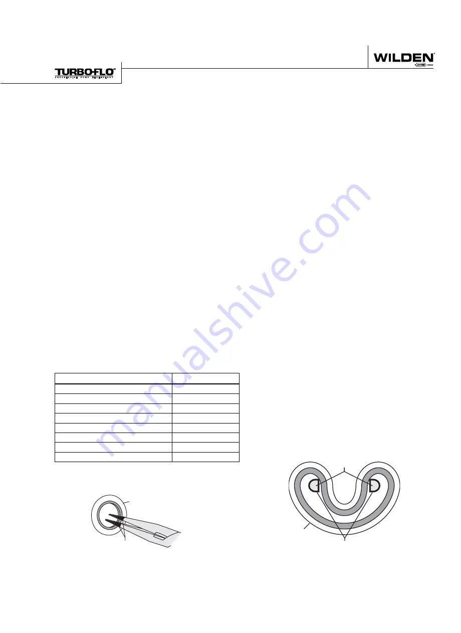
•
Open the pliers as wide as the seal diameter will allow,
then with two fi ngers pull down on the top portion of
the seal to form a kidney shape (see fi gure B).
•
Lightly clamp the pliers together to hold the seal
into the kidney shape. Be sure to pull the seal into
as tight of a kidney shape as possible. This will allow
the seal to travel down the bushing bore easier.
•
With the seal clamped in the needle nose pliers,
insert the seal into the bushing bore and position the
bottom of the seal into the correct groove. Once the
bottom of the seal is seated in the groove, release
the clamp pressure on the pliers. This will allow the
seal to partially snap back to its original shape.
•
Slowly insert the shaft with a rotating motion. This
wil l allow complete the resizing of the seal.
•
Perform these steps for the remaining seals.
Figure A
SHAFT SEAL
TAPE
Figure B
SHAFT SEAL
TAPE
NEEDLE NOSE
PLIERS


