


WIL-10160-E-11
10
P4 Clamped Plastic
SECTION 5
P4 PLASTIC SUCTION-
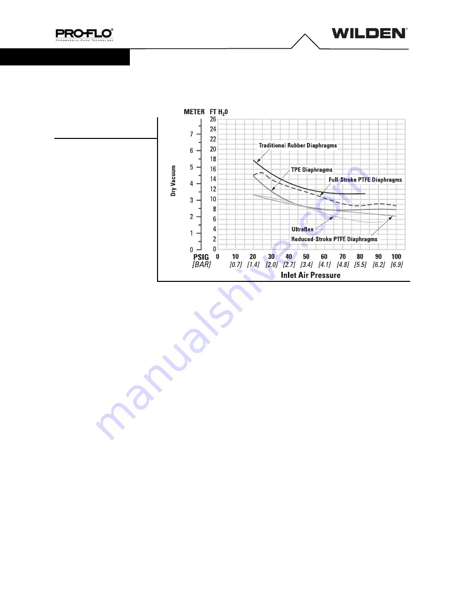
LIFT CAPABILITY
Suction-lift curves are calibrated for pumps
operating at 305 m (1,000') above sea level.
This chart is meant to be a guide only. There
are many variables that can affect your
pump's operating characteristics. The number
of intake and discharge elbows, viscosity of
pumping fluid, elevation (atmospheric
pressure) and pipe friction loss all affect the
amount of suction lift your pump will attain.
SUCTION LIFT CAPABILITY