


35/53
NT 1008-C00 07 18 P BA series e
9. SHAFT SEAL
9.1 Packing
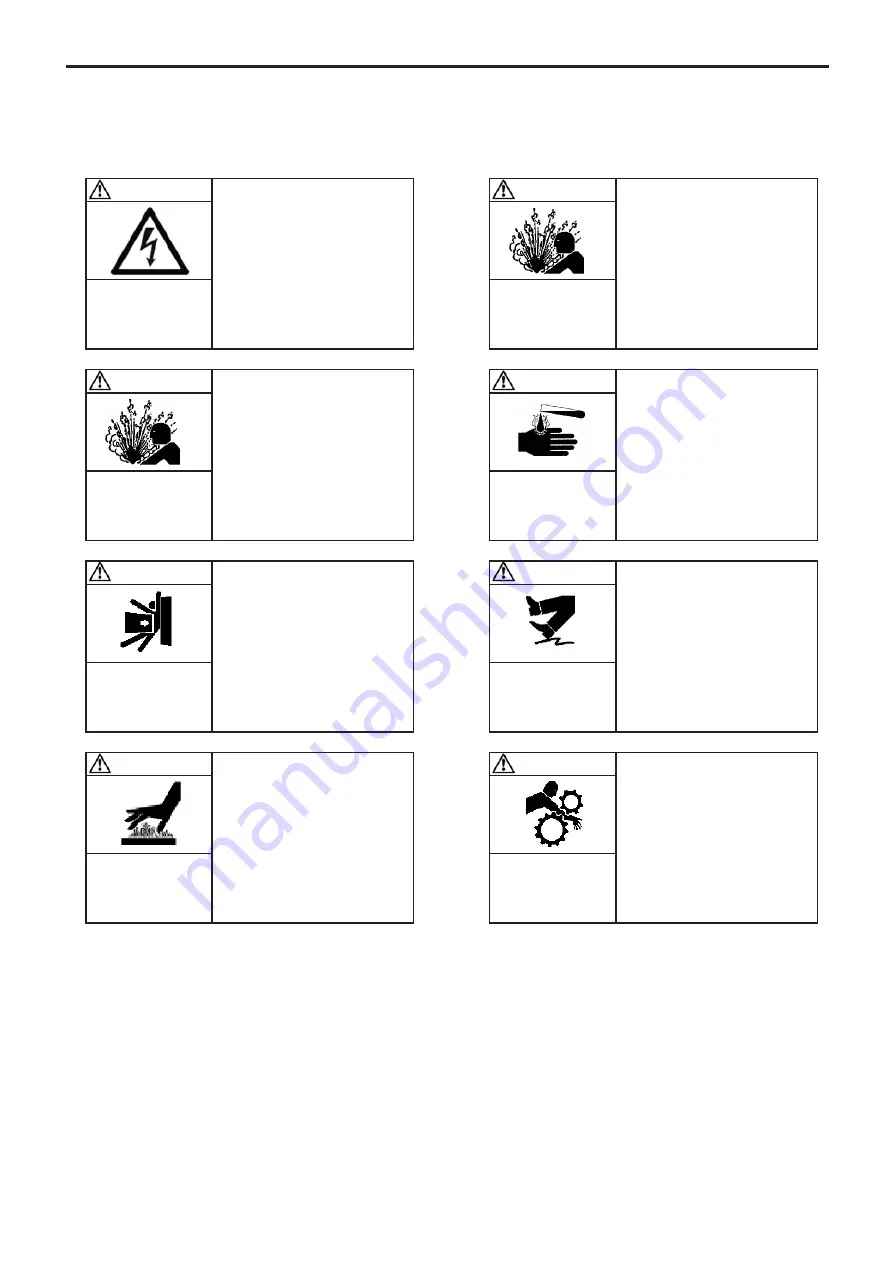
WARNING
DISCONNECT THE ELECTRICITY
SUPPLY BEFORE ANY MAINTENAN-
CE OPERATION.
Dangerous voltage.
Can cause
injury and death.
WARNING
FAILURE TO RELEASE ALL SYSTEM AIR
AND WHEN EQUIPPED, HYDRAULIC
PRESSURE, CAN CAUSE PROPERTY
DAMAGE, PERSONAL INJURY OR DEATH.
Hazardous pressure
can cause
personal injury
or property damage.
CAUTION
THE PUMP LUBRICANT IS VERY SLIPPE-
RY AND MAY CAUSE SERIOUS INJURY.
ANY SPILLS MUST BE CLEANED UP.
Slippery lubricant.
Spills should be
cleaned up.
WARNING
BE CAREFUL WITH THE WEIGHT OF
THE PARTS WHEN THEY ARE BEING
REMOVED.
The weight ot the parts
can be dangerous and may
provoke bodily injuries
or material damages.
CAUTION
THE SURFACES OF THE PUMP CAN
BE AT A TEMPERATURE LIABLE TO
CAUSE INJURY OR SEVERE DAMAGE.
Excessive temperature-
can cause injury
or severe damage.
WARNING
TAKE ALL NECESSARY MEASURES
TO RENDER ANY START-UP, EVEN
ACCIDENTAL, OF THE PUMP DURING
THE WORK IMPOSSIBLE.
Any unforeseen start-up
can cause serious
injuries or important
material damages.
WARNING
IF PUMPING HAZARDOUS OR TOXIC
FLUIDS, THE SYSTEM MUST BE FLU-
SHED PRIOR TO PERFORMING ANY
SERVICE OPERATION.
Hazardous or toxic
fluids can cause
serious injury.
WARNING
DISCONNECTING THE FLUID OR
PRESSURE CONTAINMENT COMPO-
NENTS DURING PUMP OPERATION
CAN CAUSE SERIOUS PERSONAL
INJURY, DEATH OR MAJOR PROPERTY
DAMAGE.
Hazardous pressure
can cause
personal injury
or property damage.


