


AssuredSAN Ultra48 Series Setup Guide
73
48-drive enclosure front panel LEDs
Enclosure front panel LEDs are described in two interrelated figure/table ensembles within this subsection:
•
: describes enclosure front panel LEDs (visible with the bezel installed).
•
on page 74: describes drawer panel LEDs (visible with the bezel removed).
The disk module LED is described in another related figure/table ensemble within
:
•
on page 75: describes the LED located on disk modules (visible with the bezel removed and
drawer(s) opened).
•
on page 76 describe additional disk LED behavior.
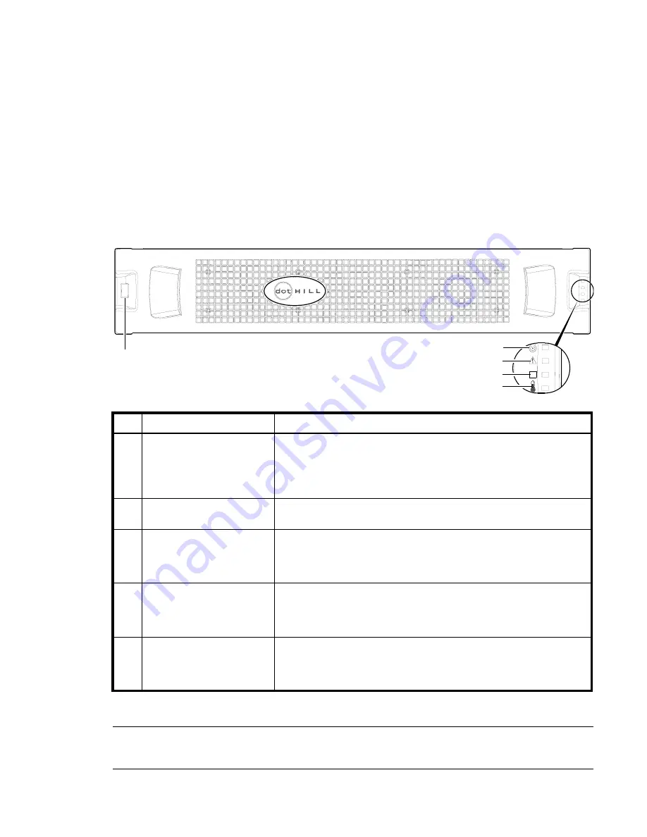
LEDs visible with enclosure bezel installed
The LEDs located on the chassis ears are described in
and are visible with the enclosure bezel
installed.
Figure 37
LEDs: 2U48 enclosure front panel
NOTE:
The enclosure front panel illustrations that follow assume that you have removed the enclosure
bezel to reveal underlying components.
LED
Description
Definition
1 Enclosure ID
Green — On
Enables you to correlate the enclosure with logical views presented by
management software. Sequential enclosure ID numbering of controller
enclosures begins with the integer 0. The enclosure ID for an attached drive
enclosure is nonzero.
2 Unit Locator
White blink — Enclosure is identified
Off — Normal operation
3 Fault/Service Required
Amber — On
Enclosure-level fault condition exists. The event has been acknowledged but
the problem needs attention.
Off — No fault condition exists.
4 FRU OK
Green — On
The enclosure is powered on with at least one power supply operating
normally.
Off — Both power supplies are off; the system is powered off.
5 Temperature Fault
Green — On
The enclosure temperature is normal.
Amber — On
The enclosure temperature is above threshold.
OK
2
3
4
5
Note: Remove this enclosure bezel to access drawers.
1
Summary of Contents for AssuredSAN 4544
Page 8: ...8 Figures ...
Page 10: ...10 Tables ...
Page 14: ...14 About this guide ...
Page 50: ...50 Connecting hosts ...
Page 52: ...52 Basic operation ...
Page 70: ...70 Troubleshooting ...
Page 90: ...90 Electrostatic discharge ...
Page 94: ...94 USB device connection ...
Page 96: ...96 SFP option for CNC ports ...
Page 100: ...100 Index ...


