


Page
|
3
REV#0002A
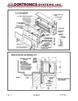
TJ1107XEDR
THRU BOLT MOUNTING IN SOLID CORE WOOD DOOR
Utilizing the template
Drill (4) 11/32”
holes
through door for knurled sex nut. Insert a 1/4-20 screw through the Z-bracket and
the face of door. Hold firmly against door by pushing directly on head of screw. Insert sex nut from opposite face and
assemble. Mount the armature to the Z-Bracket. When Z-Bracket and armature assembly is aligned correctly with the top of
the door and the centerline of the electromagnet face, tighten the (4) 1/4 -20 screws fully and securely
MACHINE SCREW MOUNTING
Door must be properly reinforced to 1/4” minimum thickness and structured for the load. Drill and tap thru reinforcing for 1/4-
20 machine screws. Insert shoulder screw/armature assembly, being sure that spring washers remain over shoulder and flat
washer is between shoulder and face of door. When armature is properly aligned with the centerline of the face of the
electromagnet, tighten the 1/4-20 machine screws fully and securely.
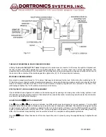
STEP 4) VERIFY LOCK & ARMATURE ALIGNMENT
Check installation and alignment of armature and electro-magnet by opening and closing door while turning system on and
off. Armature mounting surface must be in full contact with top and bottom rails of electro-magnet with center line of armature
as shown on elevation profile drawings.
ADJUSTING THE
EDR
SWITCH SENSITIVITY
If the
E
mergency
D
oor
R
elease option is installed, the EDR switch must be adjusted for correct operation. Turn the EDR
Adjust Wheel so that the switch contacts are open when the door is closed and unattended. The armature is designed to allow
a small amount of play when pressure is applied to the door in the direction of travel. Turn the EDR Adjust Wheel until the
switch contacts close when not more than 15 lbs. of force is applied in the direction of travel. Note: Local building codes may
differ. It is the installer’s responsibility to make sure that all work is in compliance with applicable guidelines.
Once the
EDR
Adjust Wheel has been set for correct operation, lock it in place by using the supplied hex key to tighten the set
screw.
Figure
3


