

(P/N) 3118.0210 Rev C 06/18 • © copyright 2010-2018
dormakaba USA Inc.
Page 2 of 4
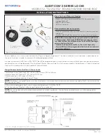
Prepare for New Installation of the Lock
(If Required)
1. Using the lock parts along with the installation template provided, establish the exact location
location (relative to the cable/spindle hole) for the drilled and tapped holes for the lock and
dial assembly.
CAUTION:
The lock case must be mounted exactly according to the template if mounted over
the cable routing hole. Otherwise, the lock case must be mounted so that no part of the case
covers the cable routing hole.
2. The cable hole diameter can be a minimum of .406” (10.3mm) to a maximum of .438”
(11.1mm). The .406” (10.3mm) diameter is recommended. The cable hole must be deburred.
3. The keypad/base assembly mounting screws require drilled and tapped holes to 3/8” (9.5mm)
depth if possible (minimum 1/4” or 6.4mm depth required.) Drill either the two horizontal
mounting holes or the two vertical holes.
4. When mounting the lock unit (i.e., integrating it in a boltwork), make sure that the lock bolt has
clearance to freely move to its end positions and that the shifting force works only in the axial
direction (direction of movement). Lateral forces should not be exerted on the lock. A minimum
clearance of 1/20” (1.27mm) is required between the flat edge of the bolt and the inside
contact edge of the strike. Refer to Figure 2.
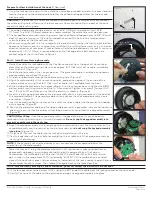
Part I: Install Front Housing Assembly
1. Route the end of the lock cable with the Picoflex connector from the back of the container
door through the cable routing hole so that approx. 6 1/2" (165.1mm) of the cable is available
from the front. (Figure 3)
2. Hold the dial assembly in the upright position. (The generator cable should be positioned at
approximately one o’clock.) (Figure 4)
3. Guide the ribbon cable through the cable receiving hole. (Figure 5).
4. Align the dial assembly with the mounting holes, and position against the outside of the
container door, ensuring that 6 1/2" (165.1mm) of cable is still available from the front.
5. While holding the dial assembly in place, attach it to the container door using the two #8-32
dial assembly mounting screws and the 9/64" Allen wrench. Tighten the screws (Torque 17-20
lbs., 1.9-2.25 N-M) and then ensure that the dial turns smoothly. (Figure 6)
6. Insert the 4-pin generator cable on the dial assembly into the 4-pin connector on the back of
the keypad assembly. The generator cable will only connect to the keypad assembly in one
orientation. (Figure 7)
7. Insert the keyed Picoflex connector on the end of the ribbon cable into the connection header
on the keypad. (Figure 8)
8. Position the generator cable and the ribbon cable around the generator in a counter-clockwise
direction to ensure that the cables will not be pinched when you attach the keypad assembly.
(Figure 9)
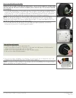
CAUTION Next Step:
Once the keypad assembly is snapped into place, it cannot be easily
removed without performing an “uninstall” procedure.
Do not snap the keypad assembly into
place when performing the next step.
9. Align the keypad assembly in the upright position and carefully insert the two catches on the
keypad assembly into the notches on the dial assembly, but
do not snap the keypad assembly
into place.
(Figure 10)
10. Plug the RJ11 end of the cable into the lock case in order to test the lock.
11. Test the operation of the lock before completing the installation of the keypad assembly by
verifying the following:
NOTE:
If the keypad is not oriented correctly, you can remove the keypad and adjust the
orientation of the dial assembly.
• Power the lock by turning the dial back and forth until simultaneous green and red flashes
display and two beeps sound to indicate that the lock is powered. Key in the Factory
Combination. (For a Model 52 or T52, enter “502550”. For a Model 252 or 552, enter a two-
digit number in the range from 01-20, followed by “502550”.) If the combination is entered
successfully, continuous green flashes display to indicate that the lock is ready to open. Rotate
the container handle to unlock. Then rotate the handle back to the locked position.
NOTE: After correctly entering a valid combination, you must retract the bolt within 4-6 seconds.
12. If the lock operation tested successfully, unplug the RJ11 end of the cable from the lock case and lay the case aside.
13. Verify that none of the cables will be pinched and snap the keypad assembly into place.
Generator cable
is at one o’clock.
Figure 3
6 1/2" of Cable
Figure 4
Figure 5
Figure 6
Figure 7
Figure 8


