Terminal 96 00
Quick Guide
4/4
04044303 - 06//2019 - DRAFT
dormakaba EAD GmbH | Albertistraße 3 | 78056 Villingen-Schwenningen | Germany
T: +49 7720 603-0 | www.dormakaba.com | Company headquarters: Villingen-Schwenningen
4.
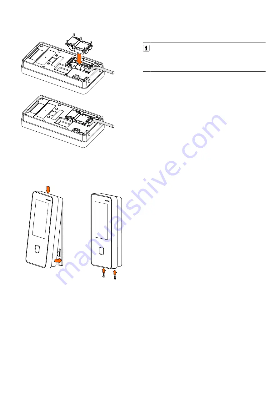
Fasten the sealing cap above the connection area using 6
screws.
Fastening the terminal to the mounting plate
1.
Hang terminal into the mounting plate at the top and press
against it at the bottom.
2.
Secure terminal housing on the mounting plate using 2 screws
M3x6.
Commissioning
Network requirements
The network must have been equipped with a working DHCP
server.
It must be possible to transfer UDP data packages unhindered to
the B-COMM server.
•
IP address 239.255.255.250, UDP port 1900 dec. and UDP port
7900 (30976 dec.) must have been enabled.
•
The SSDP service has to be enabled in the Windows service
management.
•
The SFTP connection via the standard port 22 must have been
enabled.
Automatic registration via B-COMM
Start-up of the terminal takes place largely automatically in con-
nection with the communication software B-COMM.
The device is preset at the factory for automatic registration
via B-COMM.
For communication via WLAN, the connection must have been
previously set up and activated. This is done via the system
settings.
System requirements
•
B-COMM communication software version 3.17.1 and higher.
•
Network with a working DHCP server.
Start-up procedure
1.
Connect the power supply for the device.
ð
After booting, the device cyclically reports to the B-
COMMs active in the network.
ð
At this point, until start-up by a
B-COMM is complete, the message
‘Waiting for registra-
tion’
is displayed on the display.
ð
Once the device is detected by B-COMM, the relevant
data that identifies the device will be queried.
ð
If the device is not known, it will be entered in B-COMM
under the
B-COMM Terminal Discovery client under BCTDS
(Terminal Discovery Stream).
2.
Add device in B-COMM to the desired communication channel.
3.
Provide device with the appropriate communication paramet-
ers.
ð
After having assigned the device permanently to B-
COMM, B-COMM first updates the settings of the device
and then makes a backup of the settings together with
the 'sop.ini’ licence file.
ð
The device now reports to the B-COMMs active in the net-
work that registration has been carried out, after which
the device will be removed again from the BCTDS stream
by the other B-COMMS.
4.
Load specific parameters and master records to the device.
ð
The terminal software is restarted automatically. After that,
the device is ready-to-operate.
Devices with MRD reader (multi-reader device)
Devices with MRD reader support LEGIC or MIFARE media, de-
pending on the reader type set.
For LEGIC media, the ‘LEGIC’ reader type has been factory-preset.
For processing MIFARE media, the reader type must be changed to
‘MIFARE’.
The reader type can be adjusted in the following ways:
•
Locally on the device via the test program or service interface
•
Remote via the service interface
•
Via the B-COMM communication software
CAUTION RISK OF EXPLOSION IF BATTERY IS REPLACED BY AN
INCORRECT TYPE. DISPOSE OF USED BATTERIES ACCORDING TO THE
INSTRUCTIONS.
RF exposure information: The Maximum Permissible Exposure (MPE) level has
been calculated based on a distance of d=20 cm between the device and the
human body. To maintain compliance with RF exposure requirement, use
product that maintain a 20cm distance between the device and human body.
Operating Frequency Range:BT:2402~2480MHz; RFID:13.56MHz;
Max EIRP: BT:3.52dBm;


