background image

Operation & Maintenance Manual

General Data

24

23221138 (5/08) Rev B

General Data

Unit Models

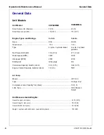
Unit Model

VHP40RMD

VHP40RMG

Rated Delivery cfm (litres/sec)  .................................. 40(19) ...................................... 40 (19)

Rated Pressure psi (kPa) .......................................... 175(1207)  ................................ 175 (1207)

Engine Types and Ratings

Kubota

Kubota

Model ......................................................................... D722 ......................................... WG572

Displacement  .........................................................

.719 L ....................................... .740 L

Type

4-cycle, 3 cylinder diesel

4-cycle, 3 cylinder 
gasoline

Net Power, BHP (kW)

15.9 (11.9)

21.7 (16.2)

Rated speed (RPM)

3000

3000

Idle speed (RPM)

2000

2000

Starting aid

Glow plugs

NA

Crankcase Capacity, Quarts (Liters)

3.34 (3.15)

3.44 (3.25)

Engine Coolant Capacity, Gallons (Liters)

1.2 (4.5)

TBD

Air Pump

Model ................................................................................................................ IR TS-10

Type .................................................................................................................. 2-stage, 4-cyl

Compressor Lube Capacity fl.oz (liters)............................................................ 50 (1.5)

Lube Type ......................................................................................................... IR All Season 

Select

Unit Measurements/Weights:

Overall Length - inch (mm) ............................................................................................. 47.75 (1213)

Overall Height - inch (mm)  ............................................................................................. 30.0 (762)

Overall Width - inch (mm)  .............................................................................................. 22.0 (559)

Weight - (system with lubricants) - pounds (kilograms) ................................................. 725 (329)

Summary of Contents for Ingersoll Rand VHP40RMD

Page 1: ...y this manual This manual must be available to the personnel who operate and maintain this machine Revised 10 12 Doosan purchased Bobcat Company from Ingersoll Rand Company in 2007 Any reference to In...

Page 2: ...2...

Page 3: ...GENERAL DATA 23 Unit Models 24 OPERATING INSTRUCTIONS 27 Set Up 28 Before Starting 28 Starting Operating 30 Unloader Pressure Adjustment 32 Speed Regulation 34 MAINTENANCE LUBRICATION 35 General 36 Sc...

Page 4: ...Maintenance Manual TITLE PAGE TROUBLE SHOOTING 45 Introduction 46 Action Plan 46 Think Before Acting 46 Do the Simplest Things First 46 Double Check Before Disassembly 47 Find and Correct Basic Cause...

Page 5: ...23221138 5 08 Rev B 5 Safety...

Page 6: ...r pressure equipment installed in or connected to the machine must have safe working pressure ratings of at least the machine safety valve rating If more than one compressor is connected to one common...

Page 7: ...s High Pressure Air can cause serious injury or death Relieve pressure before removing filler plugs caps fittings or covers Air pressure can remain trapped in air supply line which can result in serio...

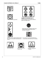
Page 8: ...instructions If you do not understand inform your supervisor Corrosion risk Hot surface Lifting point No open flame Lifting point WARNING Electrical shock risk Diesel Fuel No open flame Do not operate...

Page 9: ...ance Do not stack Do not use fork lift truck from this side WARNING Before connecting the tow bar or preparing to tow consult the operation and maintenance manual On power Off power X XBAR WARNING Mai...

Page 10: ...the operation and maintenance manual Do not remove operating and maintenance manual and manual holder from this machine Read the Operation and Maintenancemanual before operation or maintenance of thi...

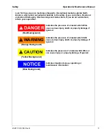
Page 11: ...erstand DANGER WARNING CAUTION NOTICE Indicates the presence of a hazard which WILL cause serious injury death or property damage if ignored Indicates the presence of a hazard which CAN cause serious...

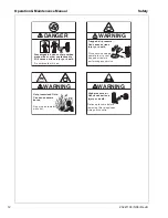
Page 12: ...e serious injury or death Relieve pressure before removing filler plugs caps fittings or coverrs WARNING Trapped air pressure Can cause serious injury or death Close service valve and operate tool to...

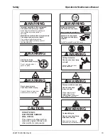
Page 13: ...n using air tools attach safety device OSHA valve at source of air supply for each tool WARNING WARNING Combustible gas Can cause serious burns blindness or death Keep sparks and open flames away from...

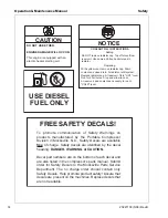
Page 14: ...verflow reservoir Use same anti freeze mixture as in radiator NOTICE USE DIESEL FUEL ONLY FREE SAFETY DECALS To promote communication of Safety Warnings on products manufactured by the Portable Compre...

Page 15: ...23221138 5 08 Rev B 15 Installation...

Page 16: ...pressor module includes either a three cylinder gasoline engine or a three cylinder diesel engine driving the air compressor pump via a double Powerband type B section belt The compressor pump is a hi...

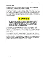
Page 17: ...a vehicle such that unrestricted airflow from motion of the vehicle may enter the unit Mounting the unit this way will cause wind milling of the fan that can damage it Mounting with this orientation m...

Page 18: ...In addition to the unit mounted Receiver Fuel Tank Module Doosan Portable Power offers two different size receiver tank options for the reciprocating compressor modules These tanks are intended to be...

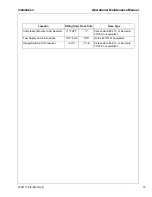
Page 19: ...ng Size Hose Size Hose Type Compressor Module to Air Receiver FNPT Parker Hannifin 213 or Aeroquip FC350 or equivalent Fuel Supply and return hoses 5 16 barb 5 16 Gates 4219G or equivalent Gauge Switc...

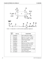
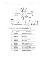
Page 20: ...0 25 NPT x 25 SAE 4 39588074 Valve Pressure Relief 5 95954038 Plug 25 NPT 6 35309210 Elbow 90 50 Tube x 50 NPT 7 22459697 Hose 50 Tube x 6 0 Ft Long 8 22459689 Swivel Reusable 50 Tube 9 22455711 Brack...

Page 21: ...5 39588074 Valve Pressure Relief 6 95954038 Plug 25 NPT 7 35309210 Elbow 90 50 Tube x 50 NPT 8 22459697 Hose 50 Tube x 6 0 Ft Long 9 22459689 Swivel Reusable 50 Tube 10 22455711 Bracket Tank Blowdown...

Page 22: ...taken to provide sufficient strain relief in the external cables and to ensure that they do not chafe on any sharp edges The compressor is protected against overheating by a thermal type discharge ai...

Page 23: ...23221138 5 08 Rev B 23 General Data...

Page 24: ...der gasoline Net Power BHP kW 15 9 11 9 21 7 16 2 Rated speed RPM 3000 3000 Idle speed RPM 2000 2000 Starting aid Glow plugs NA Crankcase Capacity Quarts Liters 3 34 3 15 3 44 3 25 Engine Coolant Capa...

Page 25: ...pressor Oil IR All Season Select 32498560 qt Compressor Oil IR All Season Select 32319758 gal Battery 12 V BCI Group Size UI 400 CCA 22660567 Engine Oil Filter 36870574 Engine Fuel Filter Diesel unit...

Page 26: ...Operation Maintenance Manual General Data 26 23221138 5 08 Rev B...

Page 27: ...23221138 5 08 Rev B 27 Operating Instructions...

Page 28: ...G Unrestricted air flow from a hose will result in a whipping motion of the hose which can cause serious injury or death A safety device must be attached to the hose at the source of supply to reduce...

Page 29: ...of pressure from a heated cooling system can result in a loss of coolant and possible severe personal injury Check the engine oil level Maintain per marks on dipstick Check the fuel level Add only CL...

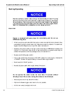
Page 30: ...the side panel under the radiator The aluminum toggle should be flipped so as to pull the valve rod outward Insert key into power switch Turn key counter clockwise to PREHEAT position and hold for 10...

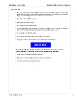
Page 31: ...d hold bypass switch Turn power switch fully clockwise to START position to crank engine Hold switch in START position for approximately 5 seconds after engine starts Return switch to RUN position Rel...

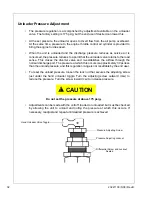
Page 32: ...stablishes the airflow through the normal discharge port The pressure at which this occurs is approximately 30 psi less than the unload pressure and this regulation range is not resettable by the end...

Page 33: ...op unit On diesel units ONLY used to activate glow plugs for starting preheat 5 Oil Pressure Lamp lights if unit shuts down due to low engine oil pressure 6 Alternator Lamp Lights if charging system m...

Page 34: ...is resting against the governor full speed stop Diesel unit For gasoline powered unit rod D should extend about 1 25 inches 32 mm from cylinder Loosen jam nut H on air actuating cylinder A and then tu...

Page 35: ...23221138 5 08 Rev B 35 Maintenance Lubrication...

Page 36: ...ervicing may consist of pre operation and post operation procedures to be performed by the operating or maintenance personnel The primary function of preventive maintenance is to prevent failure and c...

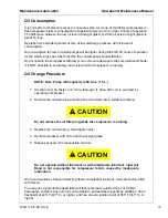
Page 37: ...is running Oil Change Procedure NOTE Note Pump refill capacity is 50 fl oz 1 5 L 1 Oil drain will be faster and more thorough if done after oil is warmed by operating compressor 2 Remove the oil drai...

Page 38: ...orter oil change intervals may be necessary if unit is operated under adverse conditions WARNING Do not under any circumstances open any drain cocks remove any plugs or the oil filler plug from the co...

Page 39: ...ement can be cleaned 5 Check new air filter elements for any shipping damage 6 Install cleaned or new elements in the reverse order to the above 7 Compressor air cleaners should be serviced at same ti...

Page 40: ...replaced numerous times without losing its sealing ability To install the nylon tubing make a mark with tape or grease pencil approximately 7 8 inch from the end of the tubing Insert the tubing into...

Page 41: ...anding 3 Use 320 grit sanding paper to repair any scratches or defects necessary 4 Scuff sand the entire area to be painted with a red scotch brite pad 5 Wipe the area clean using Duponts 3900S 6 Blow...

Page 42: ...utomatic Shutdown System Test C Air Cleaner System Visual C Compressor Oil Cooler Exterior C Clean Engine Radiator Exterior C Clean Fasteners Guards C Air Cleaner Elements WI Drive Belt Tension C C Co...

Page 43: ...justment 4 Ensure pulleys are aligned Rotate air pump slightly if necessary 5 Tighten bracket NOTE Use tension gage in combination with straight edge placed at bottom of pulley faces along side of the...

Page 44: ...44 23221138 5 08 Rev B...

Page 45: ...23221138 5 08 Rev B 45 Trouble Shooting...

Page 46: ...B Follow down that column to find the potential cause or causes The causes are listed in order 1 2 3 etc to suggest an order to follow in trouble shooting Action Plan A Think Before Acting Study the...

Page 47: ...e cause of a certain trouble and all evidence is destroyed during disassembly Check again to be sure an easy solution to the problem has not been overlooked D Find and Correct Basic Cause After a mech...

Page 48: ...Too High Unit Shutdown Defective Safety Valve Compressor Discharge Temp too High Pressure Switch set too high Loose Wire Connection Defective Discharge Air Temp Switch Fan s Will Not Run Airend Malfun...

Page 49: ...2008 Doosan Infracore International Printed in the USA Doosan Infracore Portable Power 1293 Glenway Drive Statesville N C 28625 www doosanportablepower com...

Reviews: