background image

OP000530

Inspection, Maintenance and Adjustment
4-56

Hydraulic Oil Exchange and Suction 

Strainer Cleaning

NOTE:

Based on the type of excavating being completed,
the working conditions (extremely hot or dusty) and
the extra front end attachments being used (hydraulic
breaker, etc.), the hydraulic fluid will need to be
changed more frequently.

1.

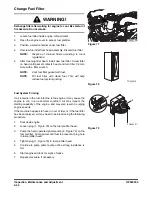
Position the machine on firm, level ground. Swing upper
structure perpendicular (90°) to wheels. Lower boom and
position bucket on ground as shown in Figure 105.

2.

Set safety lever and stand on "LOCK" position.

3.

Shut down engine.

4.

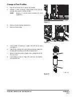
Release pressurized air from hydraulic tank by rotating
breather cap (1, Figure 108).

Figure 104 

ARO1760L

 WARNING!

The hydraulic oil will be hot after normal machine
operation. Allow the system to cool before attempting to
service any of the hydraulic components.

The hydraulic tank is pressurized. Loosen the breather cap
to allow the pressurized air to vent. After the pressure has
been released, it is safe to remove either the fill cap or
service covers.

IMPORTANT

Make sure to clean any dirt or water from the top of the
hydraulic tank, especially around the fill port and filter
ports.

Hydraulic oil change interval is 2,000 hours, only when

DOOSAN

 Genuine Oil is used. If another brand of oil is

used, guaranteed change interval is 1,000 hours.

FG008608

Figure 105 

Summary of Contents for DX190W

Page 1: ...ended that consumers periodically contact their distributors for recent documentation on purchased equipment This documentation may include attachments and optional equipment that is not available in your machine s package Please call your distributor for additional items that you may require Illustrations used throughout this manual are used only as a representation of the actual piece of equipme...

Page 2: ......

Page 3: ...intenance 1 33 Battery 1 41 Towing 1 43 Shipping and Transportation 1 44 Excavator Rated Lift Capacity Tables 1 45 Operating Controls 2 1 Component Locations 2 4 Operator s Area 2 6 Operational Controls and Panels 2 8 Instrument Panel 2 26 Multifunction Gauge and Graphic Information 2 32 Mode Selector Buttons 2 38 Setting Main Menu 2 40 Flow Control 2 49 Operation Selection Display 2 51 Heater and...

Page 4: ...l Chocks 2 76 Operation 3 1 To Handle a New Excavator 3 1 Starting and Stopping the Engine 3 2 Safety Lever 3 14 Travel 3 15 Operating Instructions 3 23 Operating Precautions 3 30 Parking Excavator 3 35 Towing Procedure 3 36 Hydraulic Breaker 3 38 Adjusting the Pump Flow 3 43 Operating Techniques 3 46 Operation Under Unusual Conditions 3 48 Inspection Maintenance and Adjustment 4 1 Preventive Main...

Page 5: ...tioning System 4 63 Inspection of Bolt And Nut Tightening Elements 4 64 Bucket 4 72 Electrical System 4 75 Engine Cooling System 4 79 Fuel Transfer Pump Option 4 81 Handling of Accumulator 4 84 Tires and Wheels 4 86 Venting and Priming Hydraulic System 4 91 Maintenance in Special Conditions 4 94 Long Term Storage 4 95 Transportation 5 1 Short Distance Self powered Travel 5 2 Trailer Loading Unload...

Page 6: ...K1024512E Table of Contents IV Brakes 6 7 Specification 7 1 Specification 7 1 Overall Dimensions 7 3 Working Range 7 5 Index 8 1 ...

Page 7: ...tions on page 1 14 4 General Hazard Information on page 1 14 5 Before Starting Engine on page 1 23 6 Machine Operation on page 1 27 7 Maintenance on page 1 33 8 Battery on page 1 41 9 Towing on page 1 43 10 Shipping and Transportation on page 1 44 11 Excavator Rated Lift Capacity Tables on page 1 45 DANGER Unsafe use of the excavator could lead to serious injury or death Operating procedures maint...

Page 8: ...n in this manual apply only to intended uses of the machine If you use your machine for any unintended uses that are not specifically prohibited you must be sure that it is safe for any others In no event should you or others engage in prohibited uses or actions as described in this manual DOOSAN delivers machines that comply with all applicable regulations and standards of the country to which it...

Page 9: ...onal injury or accidents Always observe safety precautions and follow recommended procedures CAUTION This word is used on safety messages and safety labels and indicates potential of a hazardous situation that if not avoided could result in minor or moderate injury It may also be used to alert against a generally unsafe practice WARNING This word is used on safety messages and safety labels and in...

Page 10: ...fore the safety messages in this manual and on the machine may not include all possible safety precautions If any procedures or actions not specifically recommended or allowed in this manual are used you must be sure that you and others can do such procedures and actions safely and without damaging the machine If you are unsure about the safety of some procedures contact a DOOSAN distributor ...

Page 11: ... the words Replace the illustrations if the illustrations are not visible When you clean the warning signs use a cloth water and soap Do not use solvent gasoline or other harsh chemicals to clean the safety signs Solvents gasoline or other harsh chemicals could loosen the adhesive that secures the warning sign Loose adhesive will allow the warning sign to fall off Replace any safety sign that is d...

Page 12: ...s being jacked up with boom and arm Sound the horn to alert the people nearby before operating and make sure that all persons are clear of area Controls may be changed for attachments or operator preference Try control pattern before operating FG007284 ARO1090L DANGER SERIOUS INJURY OR DEATH BY ELECTROCTION can occur if machine or attachments are not a safe distance from electrical power lines Lin...

Page 13: ...window lock it in place with lock pins on both sides Falling window can cause injury 2190 3388 190 00093 ARO1140L 190 00094 Sudden and unwanted machine movement can cause serious injury or death Always make sure when leaving operator s seat to Lower equipment to the ground Move safety lever to LOCK position Turn key switch OFF Remove key from switch 190 00693 ...

Page 14: ... caused by shortcircuiting batteries Surfuric acid in battery is poisonous It is strong enough burn skin eat holes in clothing and cause blindness if splashed eyes If you spill acid on yourself 1 Flush your skin with water 2 Apply baking soda or lime to help neutralize the acid 3 Flush your eyes with water for 10 15 minutes Get medical attention immediately 2190 2533A ARO1160L HOT OIL CAN CAUSE IN...

Page 15: ...00097 HOT COOLANT CAN CAUSE INJURY OR BLINDNESS Never loosen or open radiator cap when coolant is hot and under pressure To open cap stop engine wait until radiator is cool Then loosen cap slowly to relieve the pressure 190 00692 EXPLOSIONHAZARD Keep away from flame Do not weld on or drill into the accumulator 190 00703 190 00099 ARO1180L ...

Page 16: ...en Inspection and Maintenance 190 00695 190 00098 ARO1190L Rotating parts can cause personal injury Keep away from fan and belt when engine is run ning Stop engine before servicing 190 00694 190 00095 190 00557 190 00098 ARO1200L WARNING DO NOT OPERATE when performing inspection or maintenance 190 00695 ...

Page 17: ...OP000527 1 11 Safety 11 Warning for a Hot Surface 190 00648A 12 Caution for Hood 190 00522 190 00648 ARO1210L 190 00522 ARO1220L ...

Page 18: ...OP000527 Safety 1 12 13 Keep Out of the Swing Area 2190 3379 K1008571 14 Warnings for Front Attachments 190 00652 FG000180 2190 3379 K1008571 ARO1230L 190 00652 ...

Page 19: ...ANGER Unsafe use of the excavator while making rated lifts could cause serious potentially fatal injuries or extensive damage to the machine or nearby property Do not let anyone operate the machine unless they ve been properly trained and understand the information in the Operation and Maintenance Manual WARNING NEVER wrap a tag line around your hands or body NEVER rely on tag lines or make rated ...

Page 20: ...well if you are taking medication that makes you feel sleepy if you have been drinking or if you are suffering from emotional problems These problems will interfere with your sense of judgement in emergencies and may cause accidents When working with another operator or with a person on work site traffic duty be sure that all personnel know the nature of the work and understand all hand signals th...

Page 21: ...s cabin To ensure safety do not use the radio or music headphones when operating the machine There is danger that this may lead to a serious accident When operating the machine do not put your hands or head out of the window When standing up from the operator s seat always place safety lock lever securely in the LOCK position If you accidentally touch the work equipment levers when they are not lo...

Page 22: ... subjected is less than 2 5 m s2 Whole body The weighted root mean square acceleration to which the whole body is subjected is less than 0 5 m s2 Measurements are obtained on a representative machine using measuring procedures as described in the following standard ISO 2631 1 ISO 5349 and SAE J1166 Recommendations for Limiting Vibrations 1 Select the right machine equipment and attachments for a p...

Page 23: ...diately Always keep these parts clean Repair any damage and tighten any loose bolts Never jump on or off the machine In particular never get on or off a moving machine These actions may lead to serious injury When getting on or off the machine always face the machine and maintain three point contact both feet and one hand or one foot and both hands with the handrails and steps to ensure that you s...

Page 24: ...nozzle in constant contact with the neck of the fuel filling nozzle to provide a ground Keep fuel and other fluid reservoir caps tight and do not start the engine until caps have been secured Precautions When Handling Fluids at High Temperature Immediately after operations are stopped the coolant engine oil and hydraulic oil are at high temperature and the radiator and hydraulic tank are still und...

Page 25: ...vers are operated the clearance between the machine and the work equipment will change and this may lead to serious damage or personal injury If going between movable parts is necessary always position and secure the work equipment so that it cannot move Fire Extinguisher and First Aid Kit As a precaution if any injury or fire should occur always do the following Be sure that fire extinguishers ha...

Page 26: ... Structure or window guards Never attempt to alter or modify any type of protective structure reinforcement system by drilling holes welding remounting or relocating fasteners Any serious impact or damage to the system requires a complete integrity reevaluation Reinstallation recertification and or replacement of the system may be necessary Contact your DOOSAN distributor for available safety guar...

Page 27: ...escribe in Handling of Accumulator on page 4 84 The accumulator is charged with high pressure nitrogen gas so it is extremely dangerous if it is handled in the wrong way Always observe the following precautions Do not drill or make any holes in the accumulator or expose it any flame fire or heat source Do not weld on the accumulator or try attaching anything to it When carrying out disassembly or ...

Page 28: ...rator seat in the upper right corner of the cabin This tool can be used in case of an emergency situation that requires the breaking of glass to exit from the operator s cabin Grip the handle firmly and use the sharp point to break the glass FG000178 Figure 13 WARNING Protect your eyes when breaking the glass ...

Page 29: ...mage or cut any of these lines Check the condition of the river bed and the depth and flow of the water before operating in water or crossing a river NEVER be in water that is in excess of the permissible water depth Any type of object in the vicinity of the boom could represent a potential hazard or cause the operator to react suddenly and cause an accident Use a spotter or signal person working ...

Page 30: ...e engine compartment and around the battery They could cause a fire Remove any dirt from the window glass mirrors handrails and steps Do not leave tools or spare parts laying around in the operator s compartment The vibration of the machine when traveling or during operations may cause them to fall and damage or break the control levers or switches They may also get caught in the gap of the contro...

Page 31: ...if there is any indication that maintenance or service work is in progress or if a warning tag is attached to controls in the cabin A machine that has not been used recently or is being operated in extremely cold temperatures could require a warm up or maintenance service before start up Check gauges and monitor displays for normal operation before starting the engine Listen for unusual noises and...

Page 32: ...the machine is used without repairing the problems it may lead to unexpected injury or failure Clear all personnel from directly around machine and from the area Clear all obstacles from the machine s path Beware of hazards Be sure that all windows are clean Secure the doors and the windows in the open position or in the shut position Adjust the rear view mirrors for best visibility close to the m...

Page 33: ...hin the turning radius or direction of travel Be sure to observe the above precautions even if a travel alarm or mirrors are installed Travel Precautions Never turn the starting switch to the O OFF position when traveling It is dangerous if the engine stops when the machine is traveling It will be impossible to operate the steering Attachment control levers should not be operated while traveling D...

Page 34: ...us injury Traveling on slopes could result in the machine tipping over or slipping On hills banks or slopes carry the bucket approximately 20 30 cm 8 12 in above the ground In case of an emergency quickly lower the bucket to the ground to help stop the machine Do not travel on grass fallen leaves or wet steel plates Even slight slopes may cause the machine to slip to the side so travel at low spee...

Page 35: ...r inadequate supports when work is being done Block tires fore and aft to prevent any movement When using the machine to prevent accidents caused by damage to the work equipment and overturning because of an excessive load do not use the machine in excess of its ability in terms of the maximum load and stability determined by the structure of the machine When working at the edge of an excavation o...

Page 36: ...s indoors or in crowded areas Do not pass the bucket over the heads of workers or over the operator s compartment of dump truck Avoid High Voltage Cables Serious injury or death can result from contact or proximity to high voltage electric lines The bucket does not have to make physical contact with power lines for current to be transmitted Use a spotter and hand signals to stay away from power li...

Page 37: ...efully on Snow Ice and in Very Cold Temperatures In icy cold weather avoid sudden travel movements and stay away from even slight slopes The machine could skid off to one side very easily Snow accumulation could hide or obscure potential hazards Use care while operating or while using the machine to clear snow Warming up the engine for a short period may be necessary to avoid operating with sluggi...

Page 38: ...ing on inclines is unavoidable block the wheels to prevent movement Lower the bucket or other working attachment completely to the ground or to an overnight support saddle There should be no possibility of unintended or accidental movement When parking on public roads provide fences signs flags or lights and put up any other necessary signs to ensure that passing traffic can see the machine clearl...

Page 39: ...anger that you may get dirt or mud in your eyes or that you may slip and injure yourself When washing the machine do the following Wear shoes with nonslip soles to prevent yourself from slipping and falling on wet places Wear safety glasses and protective clothing when washing the machine with high pressure steam Take action to prevent touching high pressure water and cutting your skin or having m...

Page 40: ... most lubricants and some coolant mixtures are flammable Leaking fuel or fuel that is spilled onto hot surfaces or onto electrical components can cause a fire Store all fuels and all lubricants in properly marked containers and away from all unauthorized persons Store oily rags and other flammable material in a protective container Do not smoke while you refuel the machine or while you are in a re...

Page 41: ...se personal injury Do not allow hot oil or hot components to contact the skin Remove the hydraulic tank filter plug only after the engine has been stopped Make sure that the hydraulic tank filter plug is cool before you remove it with your bare hand Remove the hydraulic tank filter plug slowly to relieve pressure Relieve all pressure in the hydraulic oil system in the fuel system or in the cooling...

Page 42: ...in flammable fluids Do not flame cut on pipes or on tubes that contain flammable fluids Before you weld on pipes or on tubes or before you flame cut on pipes or on tubes clean the pipes or tubes thoroughly with a nonflammable solvent If heat is applied directly to rubber hoses or piping under pressure they may suddenly break so cover them with a fireproof covering Wear protective clothing Make sur...

Page 43: ...ts that have been removed from the machine in a safe place so that they do not fall Put up a fence around the attachments and take other measures to prevent unauthorized persons from entering 1 FG000335 Figure 37 FG006545 Figure 38 DANGER DOOSAN warns any user that the removal of the counterweight from the machine front attachment or any other part may affect the stability of the machine This coul...

Page 44: ...arried out with the inspection cover open but not locked there is danger that it may suddenly close and cause injury if there is a gust of wind Crushing Prevention and Cutting Prevention You should always have at least two people working together if the engine must be run during service One person needs to remain in the operator s seat ready to work the controls or stop the machine and shut off th...

Page 45: ...the pressure has been released from the circuit Failure to release the pressure may lead to serious injury Always do the following Wear protective glasses and leather gloves Fluid leaks from hydraulic hoses or pressurized components can be difficult to see but pressurized oil has enough force to pierce the skin and cause serious injury Always use a piece of wood or cardboard to check for suspected...

Page 46: ... health risk Wipe oil from your hands promptly and wash off any remaining residue Used motor oil is an environmental contaminant and may only be disposed of at approved collection facilities To prevent pollution of the environment always do the following Never dump waste oil in a sewer system rivers etc Always put oil drained from your machine in containers Never drain oil directly onto the ground...

Page 47: ...water and see a doctor at once If you accidentally drink battery electrolyte drink a large quantity of water or milk raw egg or vegetable oil Call a doctor or poison prevention center immediately When cleaning the top surface of the battery wipe it with a clean damp cloth Never use gasoline thinner or any other organic solvent or detergent Tighten the battery caps securely If the battery electroly...

Page 48: ...eries connected twelve volt batteries have a cable connecting one positive terminal on one of the 12 volt batteries to a negative terminal on the other battery Booster or charger cable connections must be made between the nonseries connected positive terminals and between the negative terminal of the booster battery and the metal frame of the machine being boosted or charged Refer to the procedure...

Page 49: ... DOOSAN distributor Never go between the towing machine and the towed machine during the towing operation It is dangerous to carry out towing on slopes so select a place where the slope is gradual If there is no place where the slope is gradual carry out operations to reduce the angle of the slope before starting the towing operation When towing a problem machine always use a wire rope with a suff...

Page 50: ...icle trailer and load must all be in compliance with local regulations governing the intended shipping route Partial disassembly or teardown of the excavator may be necessary to meet travel restrictions or particular conditions at the work site See the Shop Manual for information on partial disassembly Refer to the Transportation and Shipping section of this Operation and Maintenance Manual for in...

Page 51: ...ne is twisted and starts to rotate If the surface area of the load is large enough wind gusts can create side loads Keep the bucket hook point directly over the load Tag lines on opposite sides of the load can help FG008679 Figure 46 WARNING Let everybody be away from the boom cylinder While lifting operation boom arm bucket hoses might burst and then high pressure oil will be ejected at high spee...

Page 52: ...face An asterisk next to the lift rating indicates rated load does not exceed 87 of hydraulic capacity All other ratings have been determined not to exceed 75 of tipping capacity Do not attempt to lift or hold any load that exceeds rated load capacity at the specified distances from the machine s rotation center line and height see lift radius and lift height in the reference drawing Figure 47 The...

Page 53: ...fety IMPORTANT Select the Digging Mode switch on the Instrument Panel before using the excavator for lifting work Engine and hydraulic oil should both be fully warmed up to operating temperature before starting a lift ...

Page 54: ... 52 7 57 5 53 6 54 4 01 5 17 3 08 4 10 2 45 3 36 2 20 7 50 R Rear Dozer Only Down 9 56 9 56 7 57 7 37 6 54 5 24 5 06 4 00 4 01 3 18 3 36 2 86 7 50 R Outrigger Only Down 9 56 9 56 7 57 7 57 6 49 6 54 4 90 5 79 3 88 4 56 3 36 3 36 7 50 F Dozer R Outrigger Down 9 56 9 56 7 57 7 57 6 54 6 54 5 94 5 79 5 45 4 56 3 36 3 36 7 50 3 R Rear Dozer Only Up 9 11 5 28 6 68 3 88 5 09 3 00 4 06 2 41 3 44 2 08 7 7...

Page 55: ... 8 48 8 48 12 39 7 40 8 97 4 83 6 32 3 56 4 87 2 81 4 18 2 44 6 72 R Rear Dozer Only Down 8 48 8 48 12 39 10 59 8 77 6 60 6 18 4 76 4 75 3 71 4 08 3 21 6 72 R Outrigger Only Down 8 48 8 48 12 39 12 39 8 48 10 46 5 98 7 2 4 6 5 47 3 95 4 67 6 72 F Dozer R Outrigger Down 8 48 8 48 12 39 12 39 10 74 10 46 8 63 7 2 7 03 5 47 5 36 4 67 6 72 3 R Rear Dozer Only Up 12 31 12 31 11 96 7 50 9 04 4 89 6 37 3...

Page 56: ...trigger Only Down 27 19 27 19 16 07 17 51 10 38 12 27 7 45 8 75 7 32 7 57 25 28 F Dozer R Outrigger 27 19 27 19 17 51 17 51 13 95 12 27 8 89 8 75 7 57 7 57 25 28 5 R Rear Dozer Only Up 16 34 9 18 10 7 6 25 7 79 4 59 7 56 4 46 25 53 R Rear Dozer Only Down 15 98 12 28 10 46 8 21 7 61 6 01 7 38 5 83 25 53 R Outrigger Only Down 15 47 18 74 10 12 12 00 7 36 8 66 7 14 8 11 25 53 F Dozer R Outrigger 20 7...

Page 57: ...7 4 43 7 10 F Dozer R Outrigger Down 8 23 8 23 6 97 6 97 6 26 5 76 5 53 4 54 4 72 4 43 7 10 3 R Rear Dozer Only Up 9 41 5 20 6 64 3 84 5 07 2 99 4 05 2 40 3 78 2 24 7 33 R Rear Dozer Only Down 9 20 7 00 6 50 5 06 4 96 3 90 3 96 3 13 3 69 2 92 7 33 R Outrigger Only Down 8 92 9 73 6 29 7 54 4 80 5 68 3 83 4 50 3 57 4 20 7 33 F Dozer R Outrigger Down 9 73 9 73 7 77 7 54 6 69 5 68 6 06 4 50 4 84 4 20 ...

Page 58: ...6 8 52 10 30 6 01 7 23 4 63 5 51 4 37 5 18 6 27 F Dozer R Outrigger Down 9 45 9 45 12 76 12 76 10 30 10 30 8 34 7 23 6 69 5 51 6 18 5 18 6 27 3 R Rear Dozer Only Up 13 23 13 23 10 85 7 56 8 84 4 94 6 43 3 66 5 62 3 25 5 50 R Rear Dozer Only Down 13 23 13 23 10 85 10 77 8 84 6 72 6 28 4 86 5 49 4 29 5 50 R Outrigger Only Down 13 23 13 23 10 85 10 85 8 61 8 84 6 08 7 04 5 32 6 00 5 50 F Dozer R Outr...

Page 59: ... 8 42 8 16 6 46 24 03 R Outrigger Only Down 15 93 18 52 10 34 12 23 7 89 9 28 24 03 F Dozer R Outrigger 18 52 18 52 14 54 12 23 10 65 9 28 24 03 5 R Rear Dozer Only Up 16 25 9 11 10 68 6 24 8 13 4 80 24 30 R Rear Dozer Only Down 15 89 12 2 10 44 8 19 7 94 6 27 24 30 R Outrigger Only Down 15 38 18 64 10 10 11 98 7 67 9 03 24 30 F Dozer R Outrigger 21 34 18 64 15 82 11 98 11 45 9 03 24 30 0 GND R Re...

Page 60: ... 5 92 5 26 5 05 3 99 3 99 3 16 3 20 2 63 7 87 R Outrigger Only Down 5 92 5 92 4 90 5 46 3 86 4 54 3 20 3 20 7 87 F Dozer R Outrigger Down 5 92 5 92 5 46 5 46 5 18 4 54 3 20 3 20 7 87 3 R Rear Dozer Only Up 11 07 8 11 8 20 5 32 6 69 3 87 5 07 2 98 4 03 2 37 3 29 1 93 3 25 1 90 8 07 R Rear Dozer Only Down 11 07 11 07 8 20 7 14 6 54 5 10 4 95 3 90 3 93 3 10 3 22 2 54 3 17 2 50 8 07 R Outrigger Only D...

Page 61: ...2 88 7 13 R Outrigger Only Down 8 07 8 07 11 79 11 79 8 32 10 3 5 86 7 08 4 49 5 37 3 63 4 31 3 55 4 21 7 13 F Dozer R Outrigger Down 8 07 8 07 11 79 11 79 11 02 10 3 8 78 7 08 7 19 5 37 5 89 4 31 5 30 4 21 7 13 3 R Rear Dozer Only Up 11 05 11 05 12 98 7 26 8 86 4 73 6 24 3 47 4 79 2 73 4 34 2 49 6 46 R Rear Dozer Only Down 11 05 11 05 12 98 10 44 8 66 6 50 6 09 4 68 4 68 3 64 4 24 3 31 6 46 R Out...

Page 62: ...4 16 28 9 09 10 6 6 14 7 68 4 48 6 99 4 06 26 70 R Rear Dozer Only Down 15 04 15 04 15 91 12 20 10 36 8 10 7 50 5 90 6 82 5 36 26 70 R Outrigger Only Down 15 04 15 04 15 40 18 68 10 02 11 91 7 25 8 55 6 58 7 76 26 70 F Dozer R Outrigger 15 04 15 04 19 55 18 68 14 70 11 91 12 25 8 55 7 87 7 76 26 70 0 GND R Rear Dozer Only Up 15 90 15 41 15 83 8 71 10 36 5 93 7 58 4 38 7 19 4 16 25 98 R Rear Dozer ...

Page 63: ...00 5 00 4 78 4 11 4 67 3 14 4 14 2 48 2 63 2 23 7 47 R Rear Dozer Only Down 5 00 5 00 4 78 4 78 4 67 4 07 4 05 3 22 2 63 2 63 7 47 R Outrigger Only Down 5 00 5 00 4 78 4 78 4 67 4 67 3 92 4 61 2 63 2 63 7 47 F Dozer R Outrigger Down 5 00 5 00 4 78 4 78 4 67 4 67 4 72 4 61 2 63 2 63 7 47 4 R Rear Dozer Only Up 6 36 5 51 5 54 4 00 5 11 3 08 4 11 2 46 2 60 2 06 7 81 R Rear Dozer Only Down 6 36 6 36 5...

Page 64: ...2 10 7 55 R Rear Dozer Only Down 6 81 6 81 8 77 6 60 6 19 4 77 4 76 3 71 3 85 3 03 3 10 2 75 7 55 R Outrigger Only Down 6 81 6 81 8 48 10 47 5 99 7 21 4 60 5 48 3 72 4 40 3 10 3 10 7 55 F Dozer R Outrigger Down 6 81 6 81 11 60 10 47 9 08 7 21 7 47 5 48 6 36 4 40 3 10 3 10 7 55 2 R Rear Dozer Only Up 10 44 7 44 9 00 4 85 6 34 3 57 4 88 2 81 3 97 2 33 3 42 2 30 7 07 R Rear Dozer Only Down 10 44 10 4...

Page 65: ... 35 26 30 R Rear Dozer Only Down 15 34 12 81 10 74 8 47 7 74 6 13 5 75 5 67 26 30 R Outrigger Only Down 15 34 15 34 10 40 12 3 7 49 8 80 5 75 5 75 26 30 F Dozer R Outrigger 15 34 15 34 12 31 12 3 11 21 8 80 5 75 5 75 26 30 5 R Rear Dozer Only Up 16 34 9 16 10 72 6 26 7 82 4 61 5 94 4 24 26 54 R Rear Dozer Only Down 15 98 12 27 10 48 8 22 7 64 6 03 5 94 5 55 26 54 R Outrigger Only Down 15 47 18 75 ...

Page 66: ... Dozer R Outrigger Down 5 47 5 47 5 10 5 10 4 93 4 93 4 26 4 26 2 79 2 79 7 14 4 R Rear Dozer Only Up 6 86 5 43 5 86 3 95 5 14 3 05 4 08 2 43 2 76 2 17 7 51 R Rear Dozer Only Down 6 86 6 86 5 86 5 19 5 03 3 97 3 99 3 16 2 76 2 76 7 51 R Outrigger Only Down 6 86 6 86 5 86 5 86 4 87 5 34 3 86 4 54 2 76 2 76 7 51 F Dozer R Outrigger Down 6 86 6 86 5 86 5 86 5 34 5 34 5 13 4 54 2 76 2 76 7 51 3 R Rear...

Page 67: ...er Only Down 7 07 7 07 8 76 6 60 6 18 4 76 4 75 3 71 3 85 3 03 3 32 2 91 7 23 R Outrigger Only Down 7 07 7 07 8 48 10 47 5 98 7 21 4 59 5 47 3 72 4 40 3 32 3 32 7 23 F Dozer R Outrigger Down 7 07 7 07 11 57 10 47 9 11 7 21 7 49 5 47 6 33 4 40 3 32 3 32 7 23 2 R Rear Dozer Only Up 11 45 7 46 9 01 4 86 6 34 3 57 4 88 2 82 3 70 2 46 6 73 R Rear Dozer Only Down 11 45 10 67 8 80 6 63 6 20 4 78 4 77 3 7...

Page 68: ...01 F Dozer R Outrigger 15 84 15 84 12 36 12 36 11 17 11 17 6 11 6 11 24 01 10 R Rear Dozer Only Up 16 14 9 54 10 91 6 42 7 86 4 65 6 10 4 55 25 31 R Rear Dozer Only Down 16 14 12 68 10 66 8 40 7 68 6 07 6 10 5 95 25 31 R Outrigger Only Down 15 91 16 14 10 32 12 22 7 42 8 73 6 10 6 10 25 31 F Dozer R Outrigger 16 14 16 14 12 77 12 22 8 92 8 73 6 10 6 10 25 31 5 R Rear Dozer Only Up 16 24 9 07 10 66...

Page 69: ...3 Seat Adjustment on page 2 63 14 Ceiling Cover on page 2 67 15 Front Windows on page 2 68 16 Door Side Latch on page 2 70 17 Cabin Storage Compartments on page 2 71 18 Ashtray on page 2 71 19 Sun Visor on page 2 72 20 Hanger on page 2 72 21 Cup Holder on page 2 73 22 Door Window Holder on page 2 73 23 Emergency Glass Breaking Tool on page 2 73 24 Miscellaneous Access Covers and Doors on page 2 74...

Page 70: ...ntrols 2 2 WARNING Warning lights When any one or more of the warning lights on the control console comes ON immediately stop operation and shut down unit Investigate and correct the problem before proceeding with operation ...

Page 71: ...OP000528 2 3 Operating Controls ...

Page 72: ...OP000528 Operating Controls 2 4 COMPONENT LOCATIONS FG008697 1 2 3 4 5 6 7 8 9 10 11 12 13 14 15 16 43 22 17 18 24 23 20 21 42 25 26 41 27 30 29 32 31 33 35 38 36 34 19 40 39 Figure 1 ...

Page 73: ...g 13 Cabin 14 Seat 15 Boom 16 Boom Cylinder 17 Arm Cylinder 18 Arm 19 Bucket Cylinder 20 Guide Link 21 Push Link 22 Wheel Chocks 23 Bucket Tooth 24 Side Cutter 25 Bucket 26 Ram Cylinders 27 Front Axle 29 Swing Lock 30 Step 31 Travel Motor 32 Propeller Shaft 33 Transmission 34 Return Filter 35 Rear Axle 36 Strainer 38 Dozer Blade 39 Dozer Blade Cylinders 40 Pumps 41 Outrigger 42 Outrigger Cylinder ...

Page 74: ...OP000528 Operating Controls 2 6 OPERATOR S AREA 21 10 11 12 13 14 15 16 17 18 19 20 1 2 3 4 5 6 7 8 9 FG006121 Figure 2 ...

Page 75: ...page 2 8 7 Seat See page 2 63 8 Storage Compartment See page 2 71 9 Fuse Box See page 2 62 10 Stereo See page 2 59 11 Heater and Air Conditioner Unit 12 Dozer Blade Work Lever 13 Left Control Stand See page 2 8 14 Left Stand Tilting Lever See page 3 14 15 Left hand Work Lever Joystick See page 3 27 16 Floor Mat 17 Foot Rest 18 Steering Column 19 Brake Pedal See page 3 24 20 Accelerator Pedal See p...

Page 76: ...OP000528 Operating Controls 2 8 OPERATIONAL CONTROLS AND PANELS 1 2 3 5 4 6 7 8 9 10 11 14 16 15 29 27 25 26 24 23 18 20 17 28 22 12 13 21 19 FG006122 Figure 3 ...

Page 77: ...ng Brake Switch 12 Cabin Work Light Switch Optional 13 Lower Wiper Switch Optional 14 Heater and Air Conditional Control Panel 15 Cigarette Lighter 16 Power Socket For 12V 17 Warning Light Switch Optional 18 Overload Warning Switch Optional 19 Fuel Heater Switch Optional 20 Seat Warmer Switch Optional 21 Outrigger Selection Switch 22 Steering Console 23 Horn Button 24 Rotating Switch 25 Breaker Bo...

Page 78: ...e engine preheat cycle is completed The preheat cycle takes about twenty seconds to complete and the indicator light will turn OFF When the light turns OFF engage the starter Moving switch to this position will crank engine When engine starts release key and allow it to return to the I ON position Do not operate the starter switch for more than fifteen seconds at a time This will help prevent dama...

Page 79: ...ol is ON 5 Engine Emergency Stop Switch If the engine does not shut down when using the starter switch it can be stopped by moving the engine emergency stop switch to the I EMERGENCY STOP position O In this position the engine emergency stop system is OFF I In this position EMERGENCY STOP is selected The engine will shut down NOTE When released the switch will return to its original position O OFF...

Page 80: ...h time this power button is pressed the audio system is turned either ON or OFF If the audio system turns ON an indicator light above the button turns ON Press the up button to INCREASE volume Press the down button to DECREASE volume SCAN PWR FG000018 Figure 9 FG000019 PWR Figure 10 FG000020 Figure 11 FG000021 Figure 12 ...

Page 81: ...ion or when the parking brake switch is engaged However the ram cylinder is automatically unlocked when the transmission lever position is forward or reverse I In this position the ram cylinder is LOCKED while in travel or park mode Locking the ram cylinder cuts off the ram lock valve securing and stabilizing the equipment from moving while digging 8 Light Switch This switch is used to turn on the...

Page 82: ...eaker is activated 11 Parking Brake Switch This switch is used to park the equipment O In this position parking brake is RELEASED and the monitor light on the front instrument panel turns OFF I In this position parking brake is APPLIED and the monitor light on the front instrument panel turns ON Figure 16 O I FG002177 CAUTION Be certain that the work lights are turned OFF when traveling on the str...

Page 83: ...al This switch is used to control the lower front window wiper O In this position lower windshield wiper is OFF I In this position lower windshield wiper runs at a constant speed NOTE Operating wiper without washer fluid or when there is sand or dirt present will damage the window and wiper WARNING Set the parking brake switch in the I APPLIED position before leaving the excavator Make sure to APP...

Page 84: ...a short time pull it out and have it serviced NOTE This cigarette lighter is for 24V only Never connect a 12V electrical device to the lighter 16 Power Socket for 12 Volt This is a power socket for only 12V DC devices This socket can be used for charging a cellular phone or powering a small 12V DC electrical device Open the cap when using it NOTE This socket is designed for small electrical capaci...

Page 85: ...rn ON and a warning buzzer will sound 19 Fuel Heater Switch Optional This switch is used to activate the fuel heater system When the switch is activated the fuel is warmed depending upon the temperature of the fuel NOTE If the fuel temperature is above 5 C 41 F heating system is not activated O In this position the fuel heater system is turned OFF I In this position the fuel heater system is turne...

Page 86: ...nning for the heater to operate 21 Dozer Outrigger Selector Switch Independent Optional This switch is used to select the operational mode of front and rear work equipments If equipped Left two switches are for front equipment and right two switches are for rear equipment Each equipment is operated by individually or simultaneously as selected O In this position equipment is not selected I In this...

Page 87: ...ockwise and the right one is for clockwise 25 Booster Button Right hand Work Lever Press the lower button on the top of the right hand work lever joystick to boost the hydraulic pressure Refer to the Boost Mode on page 3 26 NOTE This button works with the breaker boost shear selector switch See 10 Breaker Boost Shear Selector Switch on page 2 14 FG006175 Figure 30 FG006176 Figure 31 WARNING Before...

Page 88: ...ker Boost Shear Selector Switch on page 2 14 27 Instrument Panel See Instrument Panel on page 2 26 28 Safety Lever See Safety Lever on page 3 14 Figure 33 FG000383 WARNING Before using any attachment in a work application be sure to check its functional control Make sure that the desired movement or action is being activated by the control e g opening closing CW CCW crowd dump etc C H E F H C POWE...

Page 89: ...ing Controls 29 Photo Sensor The photo sensor detects the radiant energy of the sun In auto mode the air conditioner will automatically adjust the air temperature based on to the detected radiant energy FG000399 Figure 36 ...

Page 90: ...pproximately on a six second intermittent cycle B Windshield washer switch When the outside area of the lever is pressed it activates the washer pump and sprays fluid onto the windshield Only while being pressed J 0 II I I II FG002181 1 8 7 6 5 4 3 2 Figure 37 Reference Number Description 1 Combination Switch 2 Transmission Selector Switch 3 Work travel Selector Switch 4 Right Turn Signal Light Ha...

Page 91: ...anel NOTE When the turn is completed the lever automatically returns to the NEUTRAL position Should it not it can be manually returned by hand E Dimmer switch a Pull up Momentarily turns ON both the low beams and high beams Returns to NEUTRAL position when released b Neutral position Normal low beams c Push down Locks into position and lights up the high beams NOTE High and low beams will only fun...

Page 92: ...ion I In this position Travel Mode is selected for street travel 4 Left Turn Signal Light Hazard Warning Light This light blinks when left turn signal is turned ON Both lights blink when warning lights are turned ON NOTE If left and light turn indicators blink together or if they blink faster than normal a light build is not operating of flasher solenoid is damaged FG002190 O I W Figure 42 CAUTION...

Page 93: ...flasher solenoid is damaged 8 Hazard Warning Light Switch This light is used when the equipment is stopped due to a malfunction or when an emergency occurs When this switch is pressed the directional indicator lights in front and back of the machine light up and flash warning others in the area At the same time the directional indicator lights on the instrument and hazard warning light switch will...

Page 94: ... 32 5 Digital Clock 6 Hour Meter 7 Charge Warning Light 8 Engine Oil Pressure Warning Light 9 Engine Coolant Temperature Warning Light 10 Engine Check Warning Light 11 Preheat Indicator Light 12 Parking Brake Indicator Light 13 Power Mode Selector Button See page 2 38 14 Trenching Mode Selector Button See page 2 38 15 Auto Idle Selector Button See page 2 39 16 Flow Control Button See page 2 39 17 ...

Page 95: ...functional check has been completed Enter the password into the text area and then engage the starter NOTE Refer to Set Password Lock and Unlock on page 2 47 for further details 1 Fuel Gauge Shows remaining fuel quantity in tank BLUE ZONE Indicates a normal fuel quantity RED ZONE Indicates that the fuel level is low If the gauge pointer moves into the red zone the fuel level symbol will turn ON an...

Page 96: ... idle heat surge may develop which will damage the engine Allowing the engine to idle will dissipate heat Check the coolant level look for a loose fan belt inspect for debris around radiator and so on When the temperature reaches the normal range the engine speed will automatically recover 3 Hydraulic Oil Temperature Gauge The colored bands indicate the temperature of the hydraulic oil WHITE ZONE ...

Page 97: ...splayed contents are as follows Refer to the Setting Main Menu on page 2 40 for time setting 6 Hour Meter The hour meter is used to indicate the total number of running hours on the engine The meter will flash every four seconds when the engine is running to indicate that it is functioning properly Figure 52 C H E F 02 05 MO 11 30 E G SPEED RPM FG000043 MM DD W HH mm FG000044 Figure 53 Display Des...

Page 98: ...e coolant overheats this light will turn ON an alarm will sound and the engine speed will be automatically reduced until coolant temperature drops Do not turn engine OFF because this will cause coolant temperature to rise and may cause engine to siege due to heat surge NOTE Check the engine coolant temperature gauge If the gauge pointer moves into the red zone the engine coolant temperature warnin...

Page 99: ...the fault 11 Preheating Indicator Light In cold weather this light indicates that the engine preheat function is operating When this indicator light turns OFF it means that the engine preheat cycle has been completed 12 Parking Brake Indicator Light When parking brake is APPLIED this light turns ON If vehicle is moved while parking brake applied a warning alarm will sound FG000045 Figure 58 HAAE20...

Page 100: ...BAR Rear pump pressure BAR NOTE See Figure 64 thru Figure 67 A digital clock is located at the top of the display By using a combination of the mode selector buttons information for filters and oils can also be displayed The display can also be set for the desired language Refer to the Setting Main Menu on page 2 40 for the language selection and information display sequences Communication Indicat...

Page 101: ...h is turned to the I ON position during a state of communication error failure the e EPOS controller will default to the following modes Power mode Standard mode Working mode Digging mode Auto idle ON Selection state Engine Speed The engine speed is numerically displayed Battery Voltage The battery voltage is numerically displayed With the engine running the reading should be between 26V 30V When ...

Page 102: ...pump is the farthest from engine flywheel housing or is the lower one of hydraulic pump It displays the reading in BARs Abnormal State Warning Symbols 1 Hydraulic Oil Overheating Warning 2 Pilot Filter Clogged Warning 3 Fuel Shortage Warning 4 Return Filter Clogged Warning 5 Air Cleaner Clogged Warning 6 Overload Warning Optional 7 Brake Oil Pressure Warning 8 Quick Clamp Released Warning FRONT PU...

Page 103: ...gged If this symbol is displayed immediately stop operation and replace the pilot filter After the pilot filter has been serviced restart machine operation to remove the warning symbol C H C E F H E G SPEED 1700 RPM FG000059 02 05 MO 11 30 C H E F E G SPEED FG000060 02 05 11 30 C H C E F H FG006167 E G SPEED 1700 RPM 2 kinds of warning displayed 4 kinds of warning displayed 6 kinds of warning disp...

Page 104: ...s displayed immediately stop operation and replace the return filter After the return filter has been serviced restart machine operation to remove the warning symbol 5 Air Cleaner Clogged Warning This symbol indicates when the air cleaner is clogged If this symbol is displayed immediately stop operation and replace or clean the air filter After the air filter has been serviced restart machine oper...

Page 105: ...nd the warning buzzer sound Figure 75 FG000253 WARNING If this warning appears on the screen and a warning buzzer sound reduce the load immediately If you continue to work the machine can be turned over or damage to hydraulic components and structural parts could occur BCS0800L Figure 76 WARNING Never operate or travel machine when this light is turned ON or when alarm is sounding Always investiga...

Page 106: ...to the I ON position the power mode is automatically defaulted to Standard Mode NOTE For further details see Mode Selection on page 3 25 2 Trenching Mode Selector Button This work mode is suitable for smooth trench or smooth trench wall Push this button to turn trenching mode ON or OFF When the trenching mode button is pushed to the ON position an indicator light above it turns ON When the trenchi...

Page 107: ... it turns ON When the auto idle selector button is pushed again it is turned OFF and the engine speed will return to the setting of the engine speed dial and will remain at this speed despite control lever position until the engine speed dial is moved 4 Flow Control Button When the button is pushed you can control the hydraulic oil flow rate The flow control button is used to set the flow rate of ...

Page 108: ...contents of the display screen Items such as language time and filter oil information can be checked and if necessary set with new information 1 Up Arrow Button Up arrow button is used to move a menu item Up or to the Left C H E F 02 05 MO 11 30 E G SPEED RPM FG000043 Figure 83 1 5 POWER 2 6 FG001339 3 1 Figure 84 FG000068 3 Figure 85 ...

Page 109: ...sed the digital readout changes NOTE When setting the main menu this button is used as the menu exit button ESC To access the menus the button must be pressed and held for three seconds NOTE When this button is used for menu exit button it is used to access to main menu or return to a previous screen from each submenu 4 Selection Button Selection button is used to set a menu or clear the operating...

Page 110: ...nt in any menu without changing the screen it will return to the normal display screen Main Menu The menu selection can be changed by pressing the UP or DOWN buttons The selected menu item will be highlighted and a cursor will appear by the menu item When the selected menu item is highlighted press the SELECT button to enter the next submenu 1 Language on page 2 43 2 Set Clock on page 2 43 3 Filte...

Page 111: ... clock submenu will appear NOTE If more than twenty seconds are spent in the menu without changing the screen it will return to the normal display screen Setting Method 1 Move the cursor to desired number by using the SELECT button When selected the number will flash 2 Set the time by using the UP or DOWN buttons Increase or decrease number MOVE Confirm and move the cursor to next number ESC Exit ...

Page 112: ... will be increased Filter Oil Info When the cursor is on Filter Oil Info press the SELECT button The filter oil information submenu will appear Each symbol can be selected by pressing the UP or DOWN buttons At the bottom of the screen the operating hour Hrs of each filter and or oil is displayed SET CLOCK MOVE FG000076 06 05 2004 06 29 Figure 95 MAIN MENU 1 Language 4 Adjust Display 5 Set Password...

Page 113: ...d to zero hour Hrs 0000 by pressing the SELECT If the SELECT button is pressed the reset will be completed and the screen will be returned to the previous menu If the ESC button is pressed the screen will be returned to the previous menu without being reset NOTE If more than twenty seconds are spent in the menu without changing the screen it will return to the normal display screen The screen is r...

Page 114: ...n be selected by using UP or DOWN buttons NOTE When the equipment shipped the default brightness is set to 50 The screen is returned to the main menu by pressing the ESC button The display is then saved MAIN MENU 1 Language 4 Adjust Display 5 Set Password 2 Set Clock 3 Filter Oil Info UP DOWN SELECT FG000080 Figure 100 Adjust Display FG000081 50 LCD TEST LCD TEST LCD TEST Figure 101 ...

Page 115: ...the SELECT button The set password submenu will appear NOTE The screen can be returned to the main menu by pressing the ESC button 3 Figure 84 Password inquiry menu will be displayed NOTE The initial password is 1111 The password can be changed within ten minutes while the starter switch is in I ON position After changing password be sure to use the changed password A three item menu will be displ...

Page 116: ...sword follow below procedure 1 Move the cursor to Change Password 2 Input desired 4 digits password using selector buttons at the first column Input the same password one more time at the second column 3 Select adoption lock or nonadoption unlock at set password menu NOTE Keep in mind never to forget password NOTE Please contact a DOOSAN distributor if you forget your password UP DOWN SELECT FG000...

Page 117: ...ton Figure 82 and Figure 107 is pressed at the normal display screen Figure 106 the flow control screen Figure 109 will be displayed Select a tool by using the breaker boost shear selector switch The symbol in the upper left corner of the display screen will change according to the position that the selector switch is in Compare the symbols shown in Figure 109 and Figure 110 Figure 106 C H E F 02 ...

Page 118: ...ges in engine rpm Escape A Press flow control button Figure 107 to return to normal display screen and save the flow rate setting B If there is no adjustment for twenty seconds the flow control screen will return to the normal display screen FLOW CONTROL ESC CANCEL FG000254 APPLY Figure 109 Breaker Flow Control Step Pump Flow Setting l min 1 38 2 61 3 80 4 91 5 101 6 133 7 142 8 149 9 165 10 168 F...

Page 119: ...u can see the application that is currently selected Power Boost Selection Breaker Selection Shear Selection Figure 112 C H E F 02 05 MO 11 30 E G SPEED RPM FG000257 Figure 113 C H E F 02 05 MO 11 30 E G SPEED RPM FG000258 Figure 114 C H E F 02 05 MO 11 30 E G SPEED RPM FG000259 ...

Page 120: ...perating Controls 2 52 Overload Alarm Selection Optional Quick Clamp Operation Selection Optional Figure 115 C H E F E G SPEED RPM FG000260 02 05 MO 11 30 Figure 116 C H E F E G SPEED RPM FG000388 02 05 MO 11 30 ...

Page 121: ...ONTROL PANEL Location of Controls and Vents The heater and air conditioner are combined into one unit in the rear cover behind the operator s seat The operator can control cabin temperature using the control panel installed in the switch panel FG007166 Figure 117 ...

Page 122: ... the system is in AUTO mode specifications can be manually changed by pushing another button If a function is manually changed the word AUTO does not appear in the LCD display but the unchanged functions will remain in AUTO mode AUTO AUTO OFF TEMP A C A C MAX OUTSIDE SEL MODE 1 3 10 7 8 9 6 5 4 2 FG000086 Figure 118 Reference Number Description 1 Automatic Temperature Control Button 2 Off Button 3...

Page 123: ... F by 0 5 C 1 F increments Temperature setting is displayed on the LCD When the system is turned ON the previously set temperature is used as a starting point 4 Temperature Unit Selector Button This button gives the choice to select either C or F 5 Mode Selector Button This button is used to select which combination air outlets will be used OFF FG000089 Figure 120 Figure 121 TEMP FG000090 SEL FG00...

Page 124: ...in from both the front and rear It will also deliver air to the lower portion of operator s cabin from under the operator s seat C Used to direct air flow to lower portion of operator s cabin and feet This mode is mainly used for heating D Used to direct air flow to the front window and to operator s feet FG002198 Figure 124 FG002199 Figure 125 FG002200 Figure 126 FG002201 Figure 127 ...

Page 125: ...remove condensation or ice on window Winter Rainy Season B B Symbol Recirculates air within the operator s compartment Used to quickly warm or cool the operator s cabin 7 Fan Speed Selector Buttons These buttons are used to control the speed of the blower fan Momentarily pressing a button changes the speed one stage Continuously pressing and holding a button repeatedly changes the speed 8 Air Cond...

Page 126: ...ored setting will be used Additional Operating Instructions A proper indoor temperature in summer is 5 6 C 10 12 F less than the outdoor temperature Operate the air conditioner for twenty thirty minutes a week to circulate the refrigerant in the system NOTE The blower button should be on Three Bars If operating the air conditioner or heater for a long time operate the air inlet selector button and...

Page 127: ... N H O F F O SOUND TUNE L AM FM 1 4 3 2 5 6 SCAN PROGRAM AST FG000108 2 3 7 9 8 5 6 10 4 1 Figure 134 Reference Number Description 1 Power Volume Control 2 Sound Mode Selector 3 Band Selection 4 Tuning Up Down 5 Scan Function Auto Store 6 Preset Station 7 Tape Ejection 8 Fast Forward Rewind 9 Tape Loading Slot 10 LCD Reference Number Description ...

Page 128: ...OP000528 Operating Controls 2 60 CD Player Optional AST DIR FG000109 Figure 135 ...

Page 129: ... deactivates the work levers With the work levers deactivated no digging operational work can be done Circuit Breaker A main circuit breaker is in the battery box It will automatically cut off in case of an electrical short circuit or overload This will prevent the electric wiring and components from being burned or damaged If the circuit breaker is cut off check all related circuits this means so...

Page 130: ...attached to the inside of the fuse box access cover indicates the function and amperage of each fuse NOTE For a further explanation see Fuse Boxes on page 4 77 Spare fuses are mounted on the inside of fuse box access cover Change a fuse if the element separates If the element of a new fuse separates check the circuit and repair the circuit HAAE2120 A Figure 139 WARNING When changing the fusible li...

Page 131: ...ht It is possible to move the seat up or down by combining adjustments forward and rear tilt Adjust the seat according to operator s size and work conditions Height adjustment is 60 mm 2 4 in 3 Suspension Adjustment Turning knob 3 Figure 141 to right makes the suspension harder Turning knob to left makes the suspension softer Adjust according to operator s weight by checking the weight indicator d...

Page 132: ...justed forward backward and up down Move it by holding both sides 8 Seat Belt Figure 142 5 8 6 9 7 FG000778 WARNING The seat belt is for the operator s safety and should always be worn Before driving the machine adjust the seat to the desired position for maximum comfort and machine control then fasten the seat belt Seat belts must be worn across the pelvic region and adjusted snugly to lessen the...

Page 133: ...e manual 10 Left and Right Control Stand Adjustment For operator s convenience the right and left control stands and seat can slide together within a 160 mm 6 3 in forward or backward travel distance Holding lever 10 Figure 145 raise it up set the seat to desired position Release lever to lock the seat in the selected position 11 Left and Right Control Stand Height Adjustment The left and right di...

Page 134: ...ed to adjust the air cushion If the switch is pressed the seat become harder and pulling it out makes the seat softer when the air is bleed out 13 Heating the Operator s Seat Optional The air suspension seat can be heated The switch on the left control stand is used to warm the seat When heating is not needed or seat is warmed turn the switch to OFF position FG000187 12 Figure 146 FG000034 O I Fig...

Page 135: ...it with a soft fabric towel Opening the Ceiling Cover 1 Lower bucket to ground 2 Set safety lever Figure 148 on LOCK 3 Pull the lock 1 Figure 149 in front center of ceiling cover and push it up with handle Closing the Ceiling Cover 1 Lower bucket to ground 2 Set safety lever Figure 148 on LOCK 3 Pull down cover with the handle Figure 149 so that the lock 1 can be locked in the bracket in the ceili...

Page 136: ... lock pin at the rear of the cabin Make sure that it is securely latched 7 Check that lock levers are securely latched in the lock position NOTE When the front upper window is open never extend your head or body through the window frame NOTE If the window happens to fall with a strong impact against the machine while some part of your body is extended out of the cabin it may result in bodily injur...

Page 137: ...securely latched in the lock position Front Bottom Window The front bottom window can be removed and stored in the rear of the cabin 1 After stowing the front upper window in the cabin ceiling remove bottom window 1 Figure 153 from cabin in direction of the arrow 2 Set bottom window in rubber holders 2 Figure 154 behind operator s seat Secure window with left and right knobs 3 with push button 4 1...

Page 138: ...secured the door to the side of the cabin when it is opened NOTE Keep the door closed and locked when machine is not in use 2 To release door from side of cabin push the latch lever 2 Figure 156 down The latch lever is to the left of the operator s seat 1 FG000196 Figure 155 2 FG000673 Figure 156 ...

Page 139: ...s interconnected with the air conditioner So it can be supplied with either warm or cool air when air conditioner is turned ON There is a separate small tray 3 Figure 158 on the right side of operator s seat ASHTRAY An ashtray 1 Figure 159 is to the right side of the operator s seat on the side of the cabin Always close ashtray after putting out a cigarette FG000209 2 1 Figure 157 3 FG000675 Figur...

Page 140: ...E Do not allow the visor to roll back up without holding it Not holding it may result in damage to the visor and retract mechanism Ceiling sun visor 3 Figure 161 slides forward and backwards Move it with handle 4 on each side When opening the ceiling cover if equipped push the sun visor into its compartment Figure 162 HANGER A hanger 1 Figure 163 is located on the upper left side of the operator s...

Page 141: ... be reduced by tightening knob 1 Figure 165 against the window EMERGENCY GLASS BREAKING TOOL The excavator is equipped with a glass breaking tool It is to the upper right corner of the cabin This tool can be used in case of an emergency situation which requires the breaking of glass to exit from the cabin Grip the handle firmly and use the sharp point to break the glass 1 FG000205 Figure 164 1 FG0...

Page 142: ...Open door until locking device 1 Figure 168 latches Closing While holding door press locking device to release lock and close door Engine Cover Open the cover and slide prop rod 1 Figure 169 in the slot 2 until it locks in notch at the end of slot to support the cover To close cover move end of prop rod out of notch so it can slide in slot 2 FG008145 1 Figure 167 FG008146 Figure 168 FG008147 2 1 F...

Page 143: ...e Completely open the dozer cylinder protection cover FG008148 Figure 170 CAUTION In order to avoid malfunction when opening dozer cylinder protection cover you must work it after fixing the facilities on a planar ground surface and then putting down the dozer blade When opening dozer cylinder protection cover take heed so that the cover would not be shut off by external shock etc ...

Page 144: ...e rear left section of battery compartment Figure 171 Make sure the upper section is facing forward Align upper structure of machine with lower frame and make sure holes are in alignment Insert lock pin into hole Figure 172 between left boom cylinder and right boom cylinder WHEEL CHOCKS A pair of wheel chocks are supplied with the machine there are stored on the lower frame directly below the cabi...

Page 145: ... of coolant fuel engine oil and hydraulic oil 2 Inspect all lubricants daily add appropriate lubricants as required 3 During operation monitor all instruments and gauges from time to time 4 Avoid an extreme engine load 5 Operate unit at 80 load until engine and all other components are at operating temperature 6 Check that work equipment is operating normally during operation 7 Check machine for l...

Page 146: ... fuel tank and fuel pre filter 3 Hydraulic system Check for hydraulic oil leaks damaged tubing and hoses and interference points of components 4 Lubrication Perform all daily and periodic maintenance services Perform services according to reading shown on hour meter 5 Safety Perform a machine walk around Make sure that no one is under the machine or performing any maintenance on it before starting...

Page 147: ...o the I ON position Figure 4 Check all indicator lights A warning buzzer will sound for about 2 seconds After 2 seconds all lights except the following will turn OFF Engine coolant temperature gauge Charging warning light Fuel gauge Hydraulic oil temperature gauge Engine oil pressure warning light Engine rpm 0 rpm digital readout FG006173 Figure 1 WARNING When leaving operator s seat set the safet...

Page 148: ... Before Starting Engine on page 3 3 2 Set engine speed control dial slightly above LOW IDLE Figure 5 3 Sound horn 4 Enter password NOTE If the security system is LOCKED a four digit password will be required to start the engine If the system is UNLOCKED no password will be required and this display screen will not appear WARNING Start the engine after sounding horn and making sure that there are n...

Page 149: ...e noticed shut down engine Normal indicators are FG000085 O I Figure 7 WARNING If the engine does not start after approximately 15 seconds of cranking release the starter switch Wait about 5 minutes and repeat above step FG006181 O I Figure 8 Figure 9 02 05 MO 11 30 E G SPEED 1700 RPM FG007104 4 5 6 7 2 3 1 CHECK P No INSTRUMENT PANEL LIGHT OR GAUGE INDICATOR READING 1 Engine Coolant Temperature G...

Page 150: ... at low idle speed until the temperature gauge registers in the blue zone again When the blue zone is reached allow the engine to idle for an additional three five minutes before shutting down the engine If not allowed to idle heat surge may develop which will damage the engine Allowing the engine to idle will dissipate heat Check the coolant level look for a loose fan belt inspect for debris arou...

Page 151: ...will return to the I ON position Figure 13 7 After the engine starts check all operating indicators to make sure that all engine systems oil pressure coolant etc are in the normal operating range If any problems are noticed shut down engine 8 Follow Hydraulic System Warm up procedures in this section See page 3 10 FG000084 O I Figure 11 FG007105 1 CHECK P Figure 12 FG000085 O I Figure 13 WARNING I...

Page 152: ...4 WARNING 1 An explosive gas is produced while batteries are in use or being charged Keep flames or sparks away from the battery area 2 Charge batteries in a well ventilated area 3 Always wear eye protection when starting a machine with jumper cables 4 Improper jump starting procedures can cause an explosion resulting in personal injury 5 Jump start vehicles on dry ground or concrete Do not jump s...

Page 153: ...cting the Booster Batteries 1 Disconnect black negative cable 2 Figure 15 from the machine frame 5 first 2 Disconnect the other end of black negative cable 2 Figure 15 from the booster batteries 3 3 Disconnect red positive cable 1 Figure 15 from the booster batteries 3 4 Disconnect red positive cable 1 Figure 15 from the machine batteries 4 ...

Page 154: ...rm and bucket cylinders about five times without a load to circulate the oil through the system Do this for five minutes 4 Check for clearance and fully raise the front attachment Swing clockwise 3 revolutions Swing counterclockwise 3 revolutions 5 Travel forward and reverse at low speed for two revolutions of the drive wheel WARNING If a problem or abnormal operation occurs immediately shut down ...

Page 155: ... minutes set at the middle of the speed range without a load Figure 20 3 Set safety lever Figure 21 and stand on UNLOCK position 4 Slowly cycle boom arm and bucket cylinders about five times without a load to circulate the oil through the system Do this for five minutes HAOB290L Figure 19 HAOB410L Figure 20 Figure 21 FG007022 Lock Unlock Figure 22 FG000380 ...

Page 156: ... drive wheel Engine Shut Down NOTE Allow engine to idle for three five minutes before shutting down the engine If not allowed to idle heat surge may develop which will damage the engine Allowing the engine to idle will dissipate heat 1 Park excavator on level and firm ground 2 Lower front end attachment to ground and make sure all operating controls are in NEUTRAL 3 Set safety lever on LOCK positi...

Page 157: ...ny coolant or oil leaks 2 Inspect front attachment and chassis frame for abnormal appearances Correct any problems 3 Fill fuel tank 4 Get rid of any accumulated flammable materials such as leaves and paper etc in engine compartment 5 Clean all mud etc from chassis frame and tires Make sure that all steps and hand holds are clean and that the operator s compartment is clean FG000175 O I Figure 27 ...

Page 158: ...work Whereas stand also must become release condition by your lowering the stand for your normal work condition NOTE When the engine is not running but the safety lever is RELEASED and the starter key is tuned ON moving the work levers joysticks may result in movement The charged accumulators in the system will provide pilot pressure for control valve spool movement FG002254 Figure 28 WARNING When...

Page 159: ... way or on the machine Sound the horn to alert workers that you are about to move the machine 7 Be sure the path is clear during travel especially when traveling in reverse gear 8 If an alarm buzzer sounds or a warning light turns ON stop immediately and determine the cause of the problem 9 If an unusual sound or smell is noticed immediately stop the machine and determine the cause of the problem ...

Page 160: ... 30 4 Make sure that the upper section is facing forwards 5 Store the front attachment in the TRANSPORT position and set the Function Lock in the TRAVEL position See Figure 31 on page 3 16 6 Set the ram cylinder toggle switch in the UNLOCK position 7 Before moving the excavator make sure that the swing lock pin has been engaged See Swing Lock Pin and Mechanism on page 2 76 This will prevent the ex...

Page 161: ...he road travel 5 During forward motion you can shift from speed range II to speed range III Downshifting from speed range III to speed range II should not be done if the machine is traveling at a high rate of speed Damage to the transmission could result 6 To stop the machine slowly release the accelerator pedal The dynamic braking action of the machine s momentum against the engine s back pressur...

Page 162: ...to fully extend the arm and lower the boom until the bucket is 20 30 cm 8 12 above the ground See Figure 34 on page 3 19 If the machine starts to slide or slip lower the bucket to the ground to regain control If the engine stalls lower the bucket make sure that all controls are in the NEUTRAL position and restart the engine 1 FG002653 Figure 32 FG008152 Figure 33 WARNING When traveling keep bucket...

Page 163: ...wn a slope test the brakes to make sure that they are fully functional 3 Never drive down a slope with the transmission in NEUTRAL 4 When driving down a slope allow the dynamic braking action of the machine s momentum against the engine s back pressure to slow the machine Step on the brake to bring the machine to a full and controlled stop Do not over use the brakes on a slope or they can burn out...

Page 164: ...n the brake to fully stop the machine 3 Be certain to set the work levers joysticks and transmission select lever to NEUTRAL 4 If you are using the manual speed control dial reduce the engine speed to LOW IDLE FG002656 Figure 35 FG002657 Figure 36 FG002185 2 F F N R R Figure 37 HAOB290L Figure 38 ...

Page 165: ... 41 8 Remove key from starter switch 9 If the machine is parked on a slope insert the wheel chocks on the downhill side of the wheels to secure the machine See Figure 34 on page 3 19 wheel chocks are supplied with the machine There are stored on the lower frame directly below the cab When the upper structure is facing the front of the machine FG006562 Figure 39 FG002178 1 O I Figure 40 FG008623 O ...

Page 166: ...e speed control dial to match the rpm setting shown on the tachometer Figure 43 3 Press the button on the end of the right hand control arm inwards Figure 44 This button will maintain the engine rpm setting dialed in by the manual engine speed control dial The foot control pedal will not affect this setting 4 Rotate the engine speed control dial to either increase or decrease travel speed Disengag...

Page 167: ...elerator Pedal for variable engine speed NOTE If the automatic speed control system has failed the e EPOS controls automatically defaults and the machine will not function at full rated capacity Engine speed can be controlled by either the manual accelerator pedal or the manual speed control dial With the travel work mode selector switch in the TRAVEL MODE position all hydraulic controls are locke...

Page 168: ...e manual engine speed control dial is at the lowest setting the accelerator pedal controls both engine speed and a hydraulic proportioning valve that controls the actual travel speed If the manual engine speed control dial has been set to a higher rpm the accelerator pedal functions only as a hydraulic proportioning valve control enabling control of only travel speed and not engine rpm Brake Pedal...

Page 169: ... Mode 1 When the starter switch is turned ON the work mode is automatically defaulted to the digging mode 2 Select the work mode using button 3 Figure 51 before starting work 3 When the work mode button 3 Figure 51 is pressed a signal sounds changing the work mode to either Digging Mode or Trenching Mode When the trenching mode is selected the LED indicator 4 Figure 51 turns ON When the digging mo...

Page 170: ...ll be turned OFF Boost Mode 1 Power boost switch is used to gain maximum digging force 2 The power boost is activated while the lower button is being pressed on top of the right hand work lever joystick The breaker boost shear selector switch must be in the O BOOST position NOTE The power boost mode does not affect forward and reverse travel Do not use this switch for more than ten seconds TRENCHI...

Page 171: ...wn NOTE The following is not a mechanical malfunction but a proper phenomenon of the excavator When operating the arm it may stop momentarily When the arm is operated the weight of the arm may cause it to move faster than the amount of oil being supplied In some cases while swinging or moving the relief valves may make some noise This is normal and does not affect the performance of the equipment ...

Page 172: ...ull lever backwards Whenever dozer blade is being used to level ground make sure to set travel speed control to LOW SPEED Attempting to use dozer blade in HIGH SPEED will cause damage to drive system FG006563 1 2 4 6 5 3 10 9 7 8 Figure 56 Reference Number Description 1 Arm Dump 2 Arm Crowd 3 Left Swing 4 Right Swing 5 Boom Down 6 Boom Up 7 Bucket Crowd 8 Bucket Dump 9 Blade Outrigger Down 10 Blad...

Page 173: ...lect switches Select the outriggers with one or more of the switches and then push the lever forward to lower the outriggers pull the lever backwards to raise the outriggers 11 Outrigger down 12 Outrigger up Two Piece Boom Option 13 Upper Boom Up 14 Upper Boom Down 2 11 FG006195 Figure 57 Chassis attachment select switches FG006204 Figure 58 FG006564 13 14 Figure 59 FG006209 13 Figure 60 ...

Page 174: ...erate unit 4 It is possible that the boom arm or bucket may come into contact with the upper or lower structure of the machine Especially tires There are digging conditions which could allow this to happen 5 Never allow any person material etc come within realm of equipment work range Always mind surroundings when working and particularly take heed when in narrow place so that rear part would not ...

Page 175: ...d 7 Do not use machine travel or swing when the bucket is in the ground to provide additional breakout force See Figure 65 8 Do not use machine weight to provide additional breakout force See Figure 66 9 When working on soft or muddy ground make sure that the machine is not sinking 10 When working close to the excavated edge make sure that the ground the machine is sitting on is solid FG006568 Fig...

Page 176: ... 13 If the excavation is in an underground location or in a building make sure that there is adequate overhead clearance and that there is adequate ventilation See Figure 70 14 Do not use the bucket as a hammer or ramming device This is dangerous and causes damage to the front attachment See Figure 71 FG006572 Figure 68 FG006573 Figure 69 Figure 70 FG006574 FG006575 Figure 71 ...

Page 177: ...ing precautions 18 Do not move dirt or objects by swinging the excavator into them This can result in structural and mechanical failures FG006576 Figure 72 WARNING Do not travel downhill with the front end attachments raised Do not travel across slopes travel straight up or down slope Use extreme caution when swinging the upper frame when positioned on a slope Allow extra swing stopping room The a...

Page 178: ... grease on bucket pins 2 It is possible to work and travel in shallow water if the ground is stable If the terrain is rough or if the water is flowing heavy it is unsafe to operate the equipment 3 When working in wet soil the equipment can sink into the soft ground Select solid ground to secure the equipment before starting work FG006578 Figure 74 IMPORTANT When working in water do not exceed a sl...

Page 179: ...t may create a serious accident Before leaving operator s seat set safety lever on LOCK position and raise left stand FG006580 1 Figure 76 WARNING Park excavator on firm level ground Avoid parking on slopes If excavator must be parked on a slope block wheels 1 using the supplied wheel chocks See Wheel Chocks on page 2 76 and place bucket teeth in ground Figure 76 FG006581 Figure 77 HAOB290L Figure...

Page 180: ...it has adequate braking capacity Never use a damaged wire rope or chain They could brake and cause a serious accident Always wear gloves when handling a chain or wire rope When towing excavator use a wire rope or chain capable of handling the load IMPORTANT Parking brake automatically operates in case when engine is stop so that you shall release the parking brake into manual mode when towing equi...

Page 181: ...e operable again by dismissal of release condition manual mode 1 Open the bleeder C of transmission and make the equipment start 2 Set engine at low speed racing change gear from neutral to stage Ⅲ and wait until grease leaks Whence wait time is about 1 min 3 Completely exhaust grease from transmission by gear change between Ⅱ Ⅲ by some 5 10 reciprocations 4 Lock bleeder C A B FG003001 Figure 80 C...

Page 182: ...ses and tubing to prevent contamination from entering hydraulic system 3 Plug and cap all connectors and fittings on breaker to prevent contamination 4 Check all hydraulic connections for signs of leaks or loose components before starting operation Hydraulic Breaker Operation NOTE Hydraulic pressure and flow settings may need to be changed Refer to the Maintenance Section of this manual for furthe...

Page 183: ...vent damage to cylinders during breaker operation 5 Do not use the breaker if the hydraulic hoses vibrate excessively Figure 84 Check the breaker s hydraulic accumulator for damage and repair as required If excavator is operated under this condition structural and hydraulic components can become damaged 6 Do not allow the breaker body to go into water if not equipped for underwater operation The b...

Page 184: ...he excavator Do not swing the breaker from side to side when operating it Figure 87 9 Do not curl the breaker tool tip into the arm or boom when traveling or parking the excavator Figure 88 FG006585 Figure 86 HGB3033L Figure 87 WARNING Operating a breaker with the upper body turned 90 to the chassis frame can result in tipping over the machine or reduction in service life FG006588 Figure 88 ...

Page 185: ...on the instrument panel Press the display selector button to show digital pressure reading A separate pressure gauge is not required 3 Adjust the relief valve pressure by turning the adjustment screw of breaker relief valve The relief valve is installed on the left side of the upper structure behind the boom Do not use the overload relief valve on the lower part of control valve for the breaker re...

Page 186: ...r is being used These intervals should be followed as opposed to regularly scheduled maintenance Attachment Operation Rate Hydraulic Oil Filter Bucket Work 100 2 000 Hours 250 Hours First Replacement 1 000 Hours After First Replacement Hydraulic Breaker Work 100 500 Hours 100 Hours These service intervals only apply when a genuine DOOSAN oil and filter are used If any other brands are used the gua...

Page 187: ...Figure 92 will be displayed 2 Use UP or DOWN buttons to adjust flow rate 3 Press SELECT button to return to normal display screen and save the flow rate setting Figure 92 FG001090 Normal Display Flow Control Display C H E F H 02 05 MO 11 30 E G SPEED 1700 RPM FLOW CONTROL ESC CANCEL APPLY Flow Control Step Pump Flow Setting l min 1 38 2 61 3 80 4 91 5 101 6 133 7 142 8 149 9 165 10 168 ...

Page 188: ...ivating Breaker with Pedal Valve 1 Select breaker with the selector switch of the right panel 2 Pressing end 1 Figure 93 is used to activate the breaker Locking the Pedal When shear or breaker is not needed the pedal can be locked by using the prop rod 3 locking device Locking is completed when the top end of the prop 3 is positioned into pedal hole A Location for UNLOCKING B Location for LOCKING ...

Page 189: ...op end of the prop 3 is positioned into pedal hole A Location for UNLOCKING B Location for LOCKING Attachment Rotation Using the Left hand Work Lever Joystick For a machine equipped with an attachment that rotates rotation is activated while one of the control buttons is being pressed on top of the left hand work lever joystick There are three buttons on top of the left hand work lever The left an...

Page 190: ...apacity decreases as the distance from the machine swing center line is increased Lifting Unknown Weight When loads are not accurately known are to be lifted the person responsible for the job shall ascertain that the weight of the load does not exceed the machine LOAD RATING CHART at the radius at which it is to be lifted It is recommended that you feel your way into any lift as a precaution agai...

Page 191: ...onsidered before attempting to pick and carry a load Align the boom with the forward direction of machine travel Maintain this boom position when turning the machine Turn only when necessary at the slowest speed and at a wide turning radius 1 Use the shortest lifting radius distance possible 2 Keep the load as close to the ground as conditions will permit 3 Provide tag lines to prevent load from p...

Page 192: ...cted temperatures Refer to the Lubrication Specifications of the engine manual for details 5 Keep fuel tank full at all times Drain condensation from tank before and after operation Drain and service fuel filter To eliminate clogging of fuel filters due to wax crystal formation in the fuel be sure that the fuel used has a cloud point specification below the lowest expected temperature 6 Lubricate ...

Page 193: ...water with a high alkali content which increases scale and rust formation 2 Check level of battery electrolyte daily Keep electrolyte above plates preventing damage to batteries Use a slightly weaker electrolyte solution in hot climates Dilute 1 28 specific gravity electrolyte as issued to 1 20 1 24 specific gravity readings at full charge Recharge batteries whenever they reach a 1 16 specific gra...

Page 194: ... often as necessary 2 Use care when servicing fuel system to prevent dust and sand from entering the tank 3 Service the air cleaner at frequent intervals check air restriction indicator daily and keep dust cup and dust valve clean Prevent dust and sand from entering engine parts and compartments as much as possible 4 Lubricate and perform services outlined on current lubrication chart on machine a...

Page 195: ...faces in good repair 4 Lubricate machine as prescribed on lubrication chart on machine or Periodic Service Table and Chart Section 4 in this manual Shorten lubricating intervals for parts subject to exposure to salt water if found necessary Operation at High Altitudes Normally operation of machine at high altitudes will be as outlined in extreme cold Before operating at high altitudes engine fuel ...

Page 196: ......

Page 197: ...eir required intervals The service cycles may need to be shortened depending on the working conditions Extremely hot or dusty conditions will require more frequent service Operational hours are determined by the amount of time accumulated on the engine hour meter on the control console in the cabin NOTE Besides the normal hour meter the multifunction gauge can be used to keep track of the hours on...

Page 198: ...ep this number on file incase the machine is stolen Component Serial Numbers There are many serial numbers on each traceable components of the machine For example the engine serial number is stamped on the top of the engine block above the starter Additional engine information is described on a label Figure 5 on the rocker cover Please make note of these numbers and their locations These will be r...

Page 199: ...ation 2 Make sure to clean up any fluid spills especially around the engine 3 Inspect all fuel lines to make sure that fittings lines filters and O rings etc are tight and are not showing signs of wear or damage 4 If the inspection or test procedure requires that the engine be running make sure to keep all unauthorized personnel away from the machine and that all industry standard safety precautio...

Page 200: ... of maintenance may require the machine to be positioned differently Always return machine to this position 1 Park on firm level ground 2 Lower bucket to ground 3 Set safety lever on LOCK position and raise stand 4 Allow engine to run at low idle for a minimum of five minutes to allow engine to cool If this is not done heat surge may occur FG006589 Figure 6 FG006403 Lock Unlock Figure 7 HAOB290L F...

Page 201: ...rk hang up a tag Do Not Touch When Performing Inspection or Maintenance on cabin door or work lever FG000175 O I Figure 9 WARNING If engine must be run while performing maintenance use extreme care Always have one person in the cabin at all times Never leave the cabin with the engine running FG006591 Do Not Touch When Perform ing Insp ection or Maintenanc Figure 10 ...

Page 202: ...2 F 30 20 10 0 10 20 30 40 50 C Engine Oil Pan Engine Oil SAE 10W 30 SAE 10W 40 SAE 15W 40 Swing Drive Case Gear Oil SAE 90 and API GL5 SAE 80W 90 and API GL5 SAE 140 and API GL5 Hydraulic Oil Tank Hydraulic Oil ISO VG 32 ISO VG 46 ISO VG 68 Fuel Tank Diesel Fuel ASTM D975 No 2 ASTM D975 No 1 Grease Fitting Grease Multipurpose Lithium Grease NLGI No 2 Cooling System Coolant Add Antifreeze 50 antif...

Page 203: ...ing to the ZF list of lubricants TE ML 05 are permitted for axles API American Petroleum Institute ACEA Association des Constructeurs Europens d Automobiles ASTM American Society of Testing and Material ISO International Standardization Organization NLGI National Lubricating Grease Institute SAE Society of Automotive Engineers IMPORTANT Do not mix oils from different manufacturers DOOSAN does not ...

Page 204: ...draulic Oil Tank Level 116 liters 30 6 U S gal System 205 liters 54 2 U S gal Transmission 2 5 liters 0 66 U S gal Swing Device 3 8 liters 1 U S gal Axle Front Differential 10 5 liters 2 8 U S gal Front Hub Reduction Gear 2 x 2 5 liters 2 x 0 66 U S gal Rear Differential 14 liters 3 7 U S gal Rear Hub Reduction Gear 2 x 2 5 liters 2 x 0 66 U S gal Symbol Description Symbol Description Lubrication ...

Page 205: ...9 Inspection Maintenance and Adjustment Description of Lubrication and Service Chart 2000h 1000h 500h 250h 50h 10h FG008698 11 20 18 19 6 5 4 21 7 2 2 1 22 23 3 27 23 24 10 12 17 8 13 9 14 15 16 22 25 26 Figure 11 ...

Page 206: ...tridge 1 V 13 Hydraulic Oil Return Filter Element 1 F 14 Pilot Filter Element 1 F 15 Hydraulic Oil Suction Strainer Strainer 1 C 16 Engine Oil Filter Cartridge 1 17 Fuel Filter Cartridge 1 F 18 Air Cleaner Outer Element 1 C Air Cleaner Inner Element 1 19 Air Conditioner Filter Outer Element 1 C Air Conditioner Filter Inner Element 1 C 20 Brake Filter Element 1 F V Maintenance and Refill C Cleaning...

Page 207: ...se Gear Oil 80w90 2 x 2 5 L F Hub Reduction Gear Case Gear Oil 80w90 2 x 2 5 L F 24 Transmission Engine Oil 15w40 2 5 L F 25 Dozer Blade Pin Grease 12 F100 W10 26 Outrigger Frame Pin Grease 10 F100 W10 27 Drive Shaft Grease 8 V Maintenance and Refill C Cleaning F First Time Exchange Only F100 Every 10 Hours For First 100 Hours W10 Every 10 Hours If Operating In Water Replacement On Every Interval ...

Page 208: ...e 4 22 Check Air Intake System 4 23 Inspect Seat Belt for Proper Operation 4 23 Inspect Structure for Cracks and Faulty Welds 4 23 Check Operation of All Switches 4 23 Check Operation of All Exterior Lights Horn and Control Console Indicator and Monitor Lights 4 24 Start Engine Check Starting Ability and Observe Exhaust Color at Start up and at Normal Operating Temperature Listen for Any Abnormal ...

Page 209: ...ck and Clean Air Conditioning Inner Filter 4 38 Clean Radiator Oil Cooler Intercooler Fuel Cooler and Air Conditioner Condenser Core 4 39 Grease Drive Shaft 4 40 Grease Front Axle Steering Knuckle 2 X 2 points 4 points 4 41 Clean Outer Filter of Air Cleaner 4 41 Change of Fuel Prefilter 4 43 Change Fuel Filter 4 44 Drain and Refill Transmission Fluid 4 45 Drain and Refill Hub Reduction Gear Oil 4 ...

Page 210: ... 59 Check Alternator and Starter 4 60 Check All Rubber Antivibration Shock Mounts 4 60 Perform and Record the Results of the Cycle Time Tests 4 60 Inspect Machine to Check for Cracked or Broken Welds or other Structural Damage 4 60 Check Adjust Valve Clearance 4 60 Check Head Bolt Torques 4 60 4 000 Hour Biennial Service Major Parts Periodic Replacement 4 61 12 000 HOUR SIX YEAR SERVICE Hose In se...

Page 211: ...ours for first 100 hours and every 50 hours thereafter See page 4 27 NOTE If the unit has been running or working in water the outrigger should be greased daily or every 10 hours Grease Boom Arm and Front Attachment Pins for first 100 hours Grease every 10 hours for first 100 hours and every 50 or 250 hours thereafter See page 4 25 NOTE If the unit has been running or working in water the front at...

Page 212: ...H mark on dipstick some must be drained to return oil to proper level 5 Add oil through engine oil fill cap 2 Figure 13 if the oil level is below the LOW mark Check Level of Hydraulic Oil Tank FG006593 1 2 Figure 13 WARNING Allow the engine to cool before checking the oil level to avoid burns by touching hot engine parts Figure 14 L H FG006334 ARO1760L Figure 15 WARNING The hydraulic oil will be h...

Page 213: ...eather cap slowly to allow the pressurized air to vent C Remove upper cover hydraulic tank and add oil 6 If oil level is above the H mark drain oil A Shut down engine and wait for the hydraulic oil to cool down B Drain the excess oil from drain valve Figure 19 at the bottom of tank into a suitable container using a hose connected to the valve NOTE Dispose of drained fluids according to local regul...

Page 214: ...ank by observing the fuel tank sight gauge 2 Figure 20 and fuel gauge in monitor panel Fill the tank using the fill tube with the proper fuel for the operating conditions NOTE See Fluid Capacities on page 4 8 for capacity 4 The excavator may be equipped with the optional battery operated fuel fill pump The pump assembly is located in the battery box Put the suction hose of the pump into the fuel r...

Page 215: ...water or sediment 4 Position a small container under fuel prefilter Drain water or sediment by opening drain valve 2 Figure 23 on bottom of bowl 1 NOTE Dispose of drained fluids according to local regulations 5 Close drain valve Check Oil Level of Swing Reduction Device NOTE When checking level using a dipstick always remove and wipe it clean before making final level check FG006598 Figure 22 FG00...

Page 216: ...OTE If oil is above HIGH mark on dipstick some must be drained to proper level 4 If the oil does not reach the L mark on the dipstick add oil through fill port 2 Figure 24 5 If the oil level exceeds the H mark on the dipstick open cap 3 Figure 26 of drain valve and connect hose 4 to the valve Drain the excessive oil into a suitable container NOTE Dispose of drained fluids according to local regula...

Page 217: ...recovery tank The normal cold engine fluid level should be between FULL and LOW marks on tank 4 If the coolant is below the LOW mark add coolant to this tank FG006625 Figure 27 IMPORTANT If running excavator in dusty area check dust net everyday and clean it if dirty WARNING If using compressed air or water to clean the dust net make sure that proper eye protection is worn WARNING Allow the engine...

Page 218: ...wn to the point that the bucket adapter is exposed See Figure 30 NOTE These instructions are only for DOOSAN OEM buckets If you are using other manufacturers buckets refer to their specific instructions Inspect Cooling Fan Blade 1 An inspection of the cooling fan is required daily Check for cracks loose bolts bent or loose blades and for contact between the blade tips and the fan shroud Check the ...

Page 219: ...tion Inspect Structure for Cracks and Faulty Welds 1 During the daily walk around inspection and when greasing the machine look for any visible damage to the machine Repair or replace any damaged parts before operating the machine Check Operation of All Switches 1 Verify working condition of all switches before starting the engine HAOA050L Figure 32 CAUTION Hot engine components can cause burns Av...

Page 220: ...isten for Any Abnormal Sounds Check Operation of All Controls 1 With the engine at rated speed operate all of the controls 2 Follow cold weather hydraulic system warm up procedures 3 Note any slow operations or unusual movements Determine the cause and repair the fault before operating IMPORTANT Cold weather operation requires that the operator fully warm up the hydraulic oil before beginning mach...

Page 221: ... greased on a 10 hour daily basis Position machine as shown below and lower the front attachment to the ground and shut down engine Press the grease fitting and inject grease with the grease gun on the marked point After injection clean off the old grease that has been purged FG006628 A C D B E Figure 34 Reference Number Description A Arm Link Joint Pin 1 Point B Link Joint Pin 2 Points C Arm Buck...

Page 222: ...Arm Bucket Joint Pin 1 Point D Bucket Link Joint Pin 1 Point E Bucket Cylinder Rod Pin 1 Point Grease Swing Bearing 1 There are three grease fittings for the swing bearing Do not over lubricate Purge old grease with new Remove all purged grease A C D B B FG003380 Figure 35 FG003381 Figure 36 FG006629 Figure 37 ...

Page 223: ...hain to the chassis frame Grease Outrigger Pins Grease every 10 hours for first 100 hours and every 50 hours thereafter NOTE If the unit has been running or working in water the outrigger should be greased on a 10 hour daily basis Position machine as shown Figure 40 and lower the outrigger leg to the ground and shut down engine Press the grease fitting and inject grease with the grease gun on the ...

Page 224: ...a suitable container NOTE Dispose of drained fluid according to local regulations NOTE Always completely fill fuel tank at end of each workday to prevent condensation from forming on the inside walls of the tank Check Engine Fan Belt for Cracks Wear and Correct Tension After First 50 Hours 1 Inspect after first 50 hours of operation and every 150 hours thereafter See page 4 28 Change Engine Oil an...

Page 225: ...osition machine as shown below and lower the front attachment to the ground and shut down engine Press the grease fitting and inject grease with the grease gun on the marked point After injection clean off the old grease that has been purged G E F A B C D FG006634 Figure 43 Reference Number Description A Boom Cylinder Head Pin 2 Points B Boom Foot Pin 2 Points C Boom Cylinder Rod Pin 2 Points D Ar...

Page 226: ...der Head Pin 2 Points B Boom Foot Pin 2 Points C Boom Cylinder Rod Pin 2 Points D Arm Cylinder Head Pin 1 Point E Boom Arm Joint Pin 2 Points F Arm Cylinder Rod Pin 1 Point A A FG008624 Figure 44 FG003391 C D C B B Figure 45 FG003393 E Figure 46 FG003394 F Figure 47 ...

Page 227: ...e belt midway between the fan pulley and alternator pulley The belt should flex approximately 10 mm 0 4 in See Figure 49 To adjust the belt loosen the alternator adjustment plate bolts adjust the belt tension and retighten the bolts FG003395 G Figure 48 FAN ALTERNATOR CRANKSHAFT COMPRESSOR 10mm 10kg FG000353 Figure 49 IMPORTANT A loose fan belt can cause engine overheating poor charging and or pre...

Page 228: ...t can be detected by the naked eye is detrimental to belt performance 5 Do not force the belts into the pulley grooves by prying with a screwdriver or pry bar This will damage the belt side cords which will cause the belts to turn and result in complete destruction of the belts in operation 6 Belts on new machines and replacement belts lose their tension as they seat into the pulley grooves Check ...

Page 229: ... torque 27 kg m 265 N m 195 ft lb 9 Install drain plug in bottom of filter housing 10 After changing breaker filter vent air from pump and check level of hydraulic oil tank Change Swing Reduction Device Oil Drain and Refill After First 250 Hours NOTE Change swing reduction device oil after 250 hours on a new machine and every 2 000 hours thereafter See page 4 53 Replace Full Flow Hydraulic Oil Fil...

Page 230: ...place brake filter after 250 hours on new machine and every 1 000 hours thereafter See page 4 49 Inspect Pins and Bushings of Front End Attachments for Signs of Wear Check Fluid Levels in Batteries and Battery Charge Levels Inspect for Any Loose or Missing Nuts and Bolts Inspect Fuel System Hose Clamps ...

Page 231: ...oticeable NOTE The upper structure must be rotated a little at a time so that the entire face of the swing gear can be lubricated Use extreme caution when performing this operation 2 If water or other contaminations are found remove the lower access cover so that the gear teeth can be thoroughly cleaned and lubricated 3 Install access covers after lubricating gear teeth WARNING Greasing swing gear...

Page 232: ...mall amount of oil around filter gasket Screw filter on head until gasket contacts head turn filter 1 2 turn more 4 Refill the engine with the correct oil through the oil fill port Figure 56 Refer to the Lubrication Table of this manual for the recommended oil for the operating conditions NOTE See Fluid Capacities on page 4 8 for capacity 5 Start engine Run engine for five minutes at LOW IDLE and ...

Page 233: ...re frequently If filter is damaged replace damaged filter with a new one NOTE All right and left call outs are based on the operator being seated in the operator s seat facing the front 1 Open the door in the left of the machine 2 Open the cover by turning the knob 1 Figure 58 in the rear of the cabin WARNING All service and inspection of air conditioning system should be performed with the starte...

Page 234: ...dle which is inside of the left rear part of the cabin 2 Use compressed air in the clean filter If the filter is damaged replaced by a new one If the filter is very dirty use a mild soap or detergent and water to clean it Figure 59 FG000342 Figure 60 FG000422 WARNING All service and inspection of air conditioning system should be performed with the starter switch in the O OFF position WARNING If u...

Page 235: ... to remove all dirt and debris NOTE Clean dust net and install it after cleaning radiator oil cooler intercooler and fuel cooler 4 Clean air conditioner condenser core with compressed air steam or water FG006639 Figure 61 WARNING If compressed air steam or water hit your body directly there is danger of injury Always wear protective glasses mask and safety shoes during the cleaning precess Make su...

Page 236: ...t Spline 1 Point 3 Front Drive Shaft Rear U joint 1 Point 4 Center Drive Shaft Front Bearing 1 Point 5 Center Drive Shaft Rear Bearing 1 Point 6 Rear Drive Shaft Front U joint 1 Point 7 Rear Drive Shaft Spline 1 Point 8 Rear Drive Shaft Rear U joint 1 Point FG003460 Figure 64 FG008155 Figure 65 FG008156 Figure 66 FG003463 Figure 67 ...

Page 237: ... indicator light Figure 69 on instrument panel comes ON the air cleaner must be serviced NOTE Replace outer filter after cleaning 5 times or every 2 000 hours 1 year of service 2 Remove and clean rubber evacuator valve 1 Figure 70 from bottom of air cleaner housing cover 2 Inspect seal lips for wear or damage Replace valve if necessary NOTE Install evacuator valve with lips parallel to the cover F...

Page 238: ...ter filter by shinning a light through it If small holes or thinner parts are found on the element after cleaning it replace the filter 7 Clean the inside of the air cleaner body and the inside of the air cleaner cover Do not use compressed air 8 Properly install the air filter and cover 9 After filter service be sure to install cover with arrows pointing UP NOTE If after cleaning the outer filter...

Page 239: ...local regulations 3 Remove the bowl using supplied tool 4 Remove the cartridge 5 Coat surface of packing 2 Figure 76 with fuel on new cartridge 1 6 Tighten the cartridge by hand until the packing comes into contact with the surface of the filter housing head 7 When it reach the surface tighten the cartridge about 3 4 of a turn more 8 Coat surface of seal 3 Figure 76 with fuel and tighten the bowl ...

Page 240: ...o the engine it may cause the engine to run in an abnormal condition Air may impact the starting capability of the engine and may also result in surging engine speeds If the machine happens to have run out of fuel or if the fuel filter has been replaced air may need to be bleed using the following procedure 1 Shut down engine 2 Loosen plug 1 Figure 79 on the fuel prefilter head 3 Pump the hand ope...

Page 241: ...hould be drained and refilled after the first 500 hours of operation or rebuild and every 2 000 hours thereafter See page 4 59 Drain and Refill Front Axle Case Oil 1 The rear axle case oil should be drained and refilled after the first 500 hours of operation or rebuild and every 2 000 hours thereafter See page 4 58 Drain and Refill Rear Axle Case Oil 1 The rear axle case oil should be drained and ...

Page 242: ...ice 1 Position the machine on firm level ground Lower the front attachment to the ground and shut down engine 2 Remove air vent plug 1 Figure 80 from swing reduction device 3 Press grease fitting and inject grease with the grease gun on the marked point 2 Figure 81 4 Install air vent plug 1 Figure 80 in swing reduction device FG006642 1 Figure 80 FG006643 2 Figure 81 ...

Page 243: ...s 5 Install new filter and a new O ring Install bypass strainer valve and spring Install service cover plate 6 Tighten the breather cap 1 Figure 83 7 Run engine for ten minutes at low idle to purge air from circuit 8 Check level in hydraulic oil tank See page 4 16 Add oil if necessary Figure 82 C H C E F H E G SPEED 1700 RPM FG000760 02 05 MO 11 30 FG006645 3 2 1 Figure 83 WARNING The hydraulic oi...

Page 244: ... 86 4 Unscrew canister 5 Figure 87 and remove O ring 3 and filter cartridge 4 NOTE The canister will be filled with oil Use caution when removing this assembly 5 Insert a new filter cartridge and O ring Apply a small amount of oil around the entire O ring and install the canister assembly onto the filter head 1 Figure 87 NOTE Used filter should always be disposed of according to local regulations ...

Page 245: ...move O ring 3 and filter cartridge 4 NOTE The canister will be filled with oil Use caution when removing this assembly 5 Insert a new filter cartridge and O ring Apply a small amount of oil around the entire O ring and install the canister assembly onto the filter head 1 Figure 87 NOTE Used filter should always be disposed of according to local regulations 6 After changing brake filter vent air fr...

Page 246: ... be performed more frequently If filter is damaged replace damaged filter with a new one NOTE All right and left call outs are based on the operator being seated in the operator s seat facing the front 1 Open the door in the left of the machine then remove four wing bolts and washers and access cover 1 Figure 90 2 Open the cover by unscrewing the knob 1 Figure 91 in the rear of the cabin WARNING A...

Page 247: ...control switch in maximum cooling position 4 Press the Internal Air Circulation switch 5 Compare the flow of bubbles in the sight glass of receiver dryer with the drawings in the following table Figure 92 FG000342 FG006774 Figure 93 WARNING Mixing of tobacco smoke and freon is deadly Do not smoke while servicing or recharging air conditioning system CAUTION Overfilling refrigerant may cause danger...

Page 248: ... and adjusting the following items Engine Compression Pressure Injection Pressure Injection Timing Amount of Refrigerant Appearance of the Sight Glass Solutions Normal Almost clear Any bubbles disappear High No bubbles are seen Charge or withdraw the system with the correct amount of HFC 134a refrigerant Low A flow of bubbles is visible ...

Page 249: ...r 1 Set a container under excavator 2 Remove cap 3 Figure 95 and install hose 4 to drain the swing reduction device oil NOTE Dispose of drained fluids according to local regulations 3 After draining oil remove hose and install cap 4 Remove breather fill cap 2 Figure 94 and add oil to H mark on dipstick 1 FG006599 1 2 Figure 94 WARNING The gear oil is very hot after the machine has been operating S...

Page 250: ...ce valve if necessary Install evacuator valve with lips parallel to the cover 3 Remove outer filter 4 Figure 98 from the air cleaner housing 4 Clean the air cleaner cover and the inside of the air cleaner housing 5 Remove inner filter 5 Figure 99 6 Clean out inside of air cleaner housing Do not use compressed air to blow out housing 7 Install new inner filter Do not clean and reuse inner element 8...

Page 251: ...ine again to allow water to completely circulate 11 After allowing engine to cool drain water and fill system with proper antifreeze mixture for ambient temperature Refer to coolant concentration table See Antifreeze Concentration Tables on page 4 80 12 Run engine without radiator cap installed so that all air will be purged from system Fill radiator to fill neck 13 Drain and fill radiator coolant...

Page 252: ...4 Release pressurized air from hydraulic tank by rotating breather cap 1 Figure 108 Figure 104 ARO1760L WARNING The hydraulic oil will be hot after normal machine operation Allow the system to cool before attempting to service any of the hydraulic components The hydraulic tank is pressurized Loosen the breather cap to allow the pressurized air to vent After the pressure has been released it is saf...

Page 253: ...rainer 5 Figure 108 on boss portion of suction pipe 6 NOTE Measurement A is 650 mm 25 59 in 10 Fill the hydraulic oil tank Check level using sight gauge on side of tank 11 Place spring 3 Figure 108 on rod 4 and assemble cover 2 12 After replacing and cleaning the hydraulic oil filter and strainer vent the system See Venting and Priming Hydraulic System on page 4 91 13 Check level of hydraulic oil ...

Page 254: ...TE See Fluid Capacities on page 4 8 for capacity 6 Clean the fill plug Inspect the fill plug O ring for deterioration or damage and replace if necessary Reinstall the fill plug Drain and Refill Front Axle Case Oil NOTE The front axle case oil should be drained and refilled after the first 500 hours of operation and at every 2 000 hours there after NOTE The oil level must be checked on level ground...

Page 255: ...nd replace if necessary Reinstall drain plug 5 Remove the fill plug 2 Figure 111 and fill to the bottom of the fill hole with approved gear oil NOTE See Fluid Capacities on page 4 8 for capacity 6 Clean the fill plug Inspect the fill plug O ring for deterioration or damage and replace if necessary Reinstall the fill plug Drain and Refill Hub Reduction Gear Oil NOTE The hub reduction gear oil shoul...

Page 256: ... necessary Reinstall the plug 7 Repeat the process for the remaining hubs Check Alternator and Starter These checks need to be completed by an authorized DOOSAN dealer Check All Rubber Antivibration Shock Mounts Perform and Record the Results of the Cycle Time Tests Inspect Machine to Check for Cracked or Broken Welds or other Structural Damage Check Adjust Valve Clearance Check Head Bolt Torques ...

Page 257: ... parts such as gaskets and O rings Use only original equipment manufacturers parts Major Component Parts Name to be Exchanged Periodically Time to Exchange Engine Fuel Hose Tank to Fuel Prefilter 2 years or 4 000 hours Fuel Hose Fuel Prefilter to Fuel Cooler Fuel Hose Fuel Cooler to ECU Fuel Hose Tank to CP Pump Heater Hose Heater to Engine Heater Hose Heater to Radiator Air Conditioner Hose Hydra...

Page 258: ... than 2 years before being discarded or installed on a machine In service lifetime of hoses fitted on a machine can never exceed 6 years but replace hoses described in Major Parts Periodic Replacement on page 4 61 every 2 years Always replace hoses having exceeded the allowed in service lifetime irrespective of the external appearance wear Always store hoses in a dark place at a maximum of 65 rela...

Page 259: ...ondenser Inspect the condenser for dust and debris Clean if necessary NOTE See Clean Radiator Oil Cooler Intercooler Fuel Cooler and Air Conditioner Condenser Core on page 4 39 Check Magnetic Clutch Check the magnetic clutch for dirt and interference Push the A C switch in order to energize magnetic clutch and check the magnetic clutch Check Belt Tension NOTE See Check Engine Fan Belt for Cracks W...

Page 260: ...16 4 24 27 264 195 6 Tightening Bolt for Pump 10 12 17 6 5 64 47 7 Tightening Bolt for Control Valve 12 4 19 11 108 80 8 Tightening Bolt for Swing Reduction Device 20 11 30 55 539 398 9 Tightening Bolt for Swing Motor 12 16 10 14 4 141 104 10 Tightening Bolt for Battery 10 2 17 6 5 64 47 11 Joint Bolt with Cab Mounting Rubber and Frame 10 20 17 6 5 64 47 Joint Bolt with Cab Mounting Rubber and Cab...

Page 261: ...d Engine 1 Pump Side Tool 24 mm Torque 27 kg m 2 Fan Side Tool 17 mm Torque 6 5 kg m 2 Joint Bolt Nut Between Engine Mounting Bracket and Frame 1 Pump Side Tool 30 mm Torque 46 kg m 2 Fan Side Tool 30 mm Torque 46 kg m FG006787 Figure 114 FG006788 Figure 115 FG006789 Figure 116 FG006790 Figure 117 ...

Page 262: ...l 24 mm Torque 27 kg m 4 Tightening Bolt for Hydraulic Oil Tank Tool 24 mm Torque 27 kg m 5 Tightening Bolt for Fuel Tank Tool 24 mm Torque 27 kg m 6 Tightening Bolt for Pump Tool 17 mm Torque 6 5 kg m Figure 118 FG006791 FG006792 Figure 119 FG006793 Figure 120 FG006795 Figure 121 ...

Page 263: ...l 19 mm Torque 11 kg m 8 Tightening Bolt for Swing Reduction Device Tool 30 mm Torque 35 kg m 9 Tightening Bolt for Swing Motor Tool 10 mm Torque 14 4 kg m 10 Tightening Bolt for Battery Tool 17 mm Torque 6 5 kg m FG006796 Figure 122 FG006797 Figure 123 FG006798 Figure 124 FG003449 Figure 125 ...

Page 264: ...Torque 6 5 kg m Joint Bolt with Cab Mounting Rubber and Cab Tool 24 mm Torque 21 kg m 12 Joint Bolt with Swing Bearing and Upper Frame Tool 30 mm Torque 55 kg m Joint Bolt with Swing Bearing and Bottom Frame Tool 30 mm Torque 55 kg m FG000454 Figure 126 FG000455 Figure 127 FG003450 Figure 128 FG003451 Figure 129 ...

Page 265: ...l 36 mm Torque 95 kg m 14 Tightening Bolt for Propeller Shaft Tool 14 mm Torque 7 kg m 15 Tightening Bolt for Travel Motor Tool 14 mm Torque 27 kg m 16 Tightening Bolt for Ram Cylinder Tool 20 mm Torque 95 kg m FG003452 Figure 130 FG008167 Figure 131 FG003454 Figure 132 Figure 133 FG006799 ...

Page 266: ...or Center Joint Tool 19 mm Torque 11 kg m 18 Tire Wheel Nut Tool 32 mm Torque 55 60 kg m 19 Front Pin Mounting Bolt Tool 24 mm Torque 27 kg m 20 Breaker Filter Optional Tool 19 mm Torque 11 kg m FG003456 Figure 134 FG003457 Figure 135 FG003458 Figure 136 FG006800 Figure 137 ...

Page 267: ...71 Inspection Maintenance and Adjustment 21 Tightening Bolt for Lower Attachment 1 Front Tool 36 mm Torque 95 kg m 2 Rear Tool 36 mm Torque 95 kg m FG006802 Figure 138 Front Attach FG006803 Figure 139 Rear Attach ...

Page 268: ...h to drive locking pin 2 and lock washer 3 out of tooth adapter 4 3 Once worn tooth has been removed use a putty knife to scrape adapter as clean as possible 4 Slide new tooth into position and insert lock washer 5 Insert locking pin into tooth and with a hammer drive pin in until lock washer seats in locking groove WARNING Due to the possibility of flying metal objects always wear safety helmet p...

Page 269: ...t link 4 out of way 3 Remove old O ring and temporarily install new O ring 1 Figure 144 onto bucket boss 2 Make sure that O ring groove on both bucket link 4 and boss have been cleaned 4 Realign arm or link with bucket pin hole and insert bucket pin 3 Figure 143 WARNING Due to possibility of flying metal objects always wear safety helmet protective gloves and eye protection when changing pins FG00...

Page 270: ...OP000530 Inspection Maintenance and Adjustment 4 74 5 Roll new O ring 1 Figure 145 into O ring groove FG006430 3 2 1 4 Figure 145 ...

Page 271: ...em immediately with large quantities of water and see a doctor at once If you accidentally drink acid drink a large quantity of water or milk beaten egg or vegetable oil Call a doctor or poison prevention center immediately When working with batteries always wear safety glasses or goggles Battery generates hydrogen gas so there is danger of an explosion Do not bring lighted cigarettes near the bat...

Page 272: ...id on the battery surface terminals and cable connectors Petroleum jelly or grease can be applied to the connectors to help prevent corrosion Battery Replacement When the charging indicator indicates transparency state replace the battery The batteries should always be replaced in pairs Using an old battery with a new one will shorten the life span of the new battery Fuses 1 The fuses in the fuse ...

Page 273: ...function and amperage of each fuse Spare fuses are mounted on the inside of fuse box s cover One each of a 10A 15A 20A and 30A Change a fuse if the element separates If the element of a new fuse separates check the circuit and repair the circuit CAUTION Before replacing a fuse be sure to turn starter switch to O OFF position FG000110 Figure 149 CAUTION Always replace fuses with the same type and c...

Page 274: ...op Lamp 10A 5 Forward Reverse Cruise Switch 10A 5 Quick Clamp Option Breaker Option 10A 6 Beacon Option 12v Power Socket 10A 6 Horn 10A 7 Room Lamp Hazard Position Lamp Turn Signal Lamp 10A 7 Position Lamp LH 10A 8 Starter Switch Hour Meter 10A 8 Position Lamp RH 10A 9 Head Lamp 30A 9 Cabin Lamp Option 30A 10 Airconditioner Heater 20A 10 Spare 20A 11 Fuel Heater 20A 11 e EPOS Controller 20A 12 Sea...

Page 275: ...t Engine overheating is often caused by bent or clogged radiator fins The spaces between the fins can be cleaned by use of air or water under pressure When straightening bent fins use care not to damage the tubes or break the bond between the fins and the tubes Heavy duty diesel engines require a balanced mixture of water and antifreeze Drain and replace the mixture every year or 2 000 hours of op...

Page 276: ...he blue green color makes it very difficult to tell the difference of what type of antifreeze is in a cooling system The colors are only a dye added to the clear antifreeze Do not rely on color Keep careful machine records of what brand and type of antifreeze is used in the unit If you are unsure of what type of antifreeze is in the system drain and flush the system NOTE Do not mix ethylene glycol...

Page 277: ...y for diesel fuel Do not use refueling pump for other types of fuel which have a low flash point Do not use refueling pump for fuel contaminated with water or high humidity Moisture in pump mechanism can cause rust and can create pump failure Always operate pump using strainer installed on inlet hose This will prevent any foreign materials from being introduced into pump Always maintain pump and a...

Page 278: ...l tank A thermal limiter built into the motor will automatically shut off power if motor is overheating to protect it from being damaged IMPORTANT If there are any sign of leakage while operating transfer pump inspect the following components to prevent any fires or hazardous fuel spills Check all hoses leading to and from the transfer pump Check all hose clamps Check transfer pump inlet port FUEL...

Page 279: ...x on front side to I ON position NOTE Transfer pump rate of flow is approximately 35 liters minute 9 24 U S gpm Use extra care not to overfill fuel tank so that fuel does not over flow 4 Once fuel transfer is completed immediately turn switch to O OFF position to stop pump 5 Lift inlet hose 5 Figure 151 from fueling source and turn switch to I ON position for two three seconds to drain remaining f...

Page 280: ...from the circuit To release pressure turn the starter switch to the I ON position and operate all hydraulic control levers and press the service brake pedal Even though the engine is shutdown hydraulic actuated components may move while releasing pilot pressure and emergency brake is applied during pressing service brake pedal Keep all personnel away from excavator while performing this operation ...

Page 281: ...und 2 Set parking brake switch to the I position This will ensure that the parking brake is APPLIED 3 Set safety lever and stand on LOCK position 4 Shut down engine 5 Wheel chock is installed under the tires to secure the machine 6 Release the brake line pressure by stepping on the service brake pedal several times 7 Open the left door of the machine 8 Remove accumulator by unscrewing it slowly FG...

Page 282: ...ine or when working machine Check tires for damage and embedded objects Check valve stems for damage Check Tire for Damage Figure 155 Tire Dimension Working Pressure Remarks Front Tire Rear Tire 10 00 20 14PR 6 75 7 0 kg cm2 96 100 psi 6 75 7 0 kg cm2 96 100 psi Standard WARNING Improper servicing or changing tires and rims can cause explosion resulting in serious injury or death Do not service or...

Page 283: ...re When mounting tires be certain that tires are mounted with direction of rotation mark facing in proper direction If no rotation direction arrow is visible examine tread marks and position them to face the front of machine for proper traction and wear NOTE Unmatched tires will cause uneven wear and put unnecessary load on the final drive Use recommended matched tires for proper wear and performa...

Page 284: ...n part shall face inner tire rim side 5 Remove tire set outer and inner tires 2 out of axle hub 3 after releasing wheel nut 1 by means of wheel wrench FG006785 Figure 159 2 4 1 FG003431 3 4 6 7 5 2 Figure 160 Reference Number Description 1 Wheel Nut 2 Outer Tire Rim 3 Rubber Spacer 4 Inner Tire Rim 5 Outer and Inner Tire Assembly Bolt 6 Outer and Inner Tire Assembly Nut 7 Outer and Inner Tire Asse...

Page 285: ...tire on flat ground surface and then lay it so that rubber spacer come to central part of inner tire upon inner tire ring NOTE Assemble so that rubber spacer protrusion part shall face inner tire rim side 9 Place outer tire on rubber spacer while taking heed to outer and inner tire assembly bolt holes and then fasten tire assembly bolt 4 tightening torque of 11 Kg m FG003433 4 4 Figure 162 FG00343...

Page 286: ...n Figure 167 when tightening wheel nuts Tighten to specified torque Tightening torque 55 60 kg m 12 Run machine forward and backward several times to ensure proper assembly and seating of the washers Retighten wheel nuts to ensure proper torque torque 55 60 Kg m 13 Once again tighten tire assembly bolts 4 tightening torque 11 Kg m after completion of wheel nut tightening 4 3 6 FG003437 Figure 166 ...

Page 287: ...will pressurize the hydraulic oil tank and system 5 Slowly loosen vent plug Figure 169 several turns until hydraulic oil flows out of plug This shows that air has been released 6 Tighten the plug Figure 169 Hydraulic Cylinders 1 Run engine at low idle Extend and retract each cylinder to within 100 mm 4 in of fully stroking it 4 5 times 2 Operate fully extend and retract each cylinder 3 4 times 3 R...

Page 288: ...ch to the 3rd gear of high speed 3 Open breeders A and B for about 20 seconds at the same time 4 Close both breeders 5 Shift the driving speed switch to the 2nd gear of low speed 6 Open breeder B for about 20 seconds Do not open breeder C 7 Close breeder B 8 Repeat steps 2 through 7 until hydraulic oil contains no bubble which means that air is ejected completely If hydraulic still contains bubble...

Page 289: ...r of other brake lines General Venting 1 After venting air from all components shut the engine down and check the hydraulic oil level Fill hydraulic oil tank to H mark on sight gauge 2 Start engine and operate all controls again run engine for five minutes to ensure all systems have been vent and purged of air Set engine speed to LOW IDLE and check hydraulic oil level again Add oil as necessary 3 ...

Page 290: ...edded dirt and dust Clean the fuel system intake strainer and fuel filter more frequently Inspect and clean as required the starter and alternator Operating in rocky terrain Check the undercarriage and track assemblies for damage or excessive wear Inspect for loose or damaged fittings or bolts Relax track tension On a more frequent basis inspect the front end attachments for damage or excessive we...

Page 291: ...t oil to all of the control linkages and control cylinders control valve spools etc Battery Remove the battery from the excavator or remove the battery leads from the battery to fully charge and store Cooling System Inspect the coolant recovery tank to make sure that the antifreeze level in the system is at the correct level Every 90 days use a hydrometer to measure the protection level of the coo...

Page 292: ...OP000530 Inspection Maintenance and Adjustment 4 96 ...

Page 293: ...rotate the upper structure once the counterweight or front attachment has been removed WARNING 1 Loading or unloading the machine can be a dangerous operation Make sure to run the engine at the lowest speed setting and travel at the slowest speed possible 2 Make sure that the ramp being used is capable of handling the weight of the machine If required add blocking under the ramp for additional sup...

Page 294: ...ke sure to engage the Swing Lock pin to secure the upper frame assembly before traveling more than a very short distance See Swing Lock Pin and Mechanism on page 2 76 3 If you have to travel across a bridge make sure that its capacity is rated for the weight of the machine and that it is wide enough Add extra bracing as required ...

Page 295: ... travel speed selector switch to I position and step on the accelerator pedal slowly 5 The unit does not require disassembly for normal over the road transportation If the boom and arm need to be removed the counterweight will place more weight to the rear of the machine Make sure to back the excavator onto the trailer so that the counterweight end of the excavator is positioned on the ramp first ...

Page 296: ... the excavator from accidentally rotating during transportation 11 Make sure to secure the excavator onto the trailer before transporting Use chains or cable tie downs as required by local transportation laws Use the wheel chocks supplied with the machine to secure machine See Wheel Chocks on page 2 76 12 Refer to the Dimensions for Transportation table for overall machine height and width measure...

Page 297: ...sistance Never attempt to perform an adjustment disassembly or repair on hydraulic electric and electronic systems without first contacting your service center ENGINE Problem Cause Remedy Starter does not operate Low battery power Charge battery Poor terminal contact Clean and tighten connections Starter switch failure Replace switch Starter relay failure Replace relay Starter control failure Repl...

Page 298: ...Clogged or dirty fuel injectors Clean injectors Engine has poor power Clogged air intake system Clean system and replace filter Clogged or dirty fuel injectors Clean injectors Fuel filters clogged Replace filters Engine speed control cable out of adjustment Readjust Injection pump out of adjustment Contact your DOOSAN dealer Valve backlash faulty Adjust backlash Engine runs hot Low coolant level A...

Page 299: ...quired Suction filter clogged Clean filter Hydraulic pumps faulty Contact your DOOSAN dealer Main relief pressure too low Contact your DOOSAN dealer Hydraulic pumps excavating Bleed air from hydraulic pumps Only one or two actions have little or no power Overload relief pressure too low Reset pressure Makeup check valve leaking Clean or replace as required Control valve spool faulty Replace valve ...

Page 300: ...or bad Tighten or replace belt Loose or corroded terminals Tighten or replace as required Alternator faulty Repair or replace as required Low battery power Internal battery short Replace battery Short circuit in wiring Repair as required Engine speed is not controllable Speed control dial failure Replace control dial Throttle controller failure Replace controller Speed control motor failure Repair...

Page 301: ...ission control valve failure Repair or exchange Transmission failure Repair Center joint leaking Repair or exchange Brake will not release Repair Travel motor failure Repair Hydraulic accelerator valve failure Repair Wrong pilot line connection Repair Transmission control pressure set too low Repair Forward reverse solenoid valve failure Repair or exchange Travel speed is too low Control valve set...

Page 302: ...e Electric system damage Repair Cruise control will not release when brake pedal is pressed Stop light pressure switch failure Repair or exchange Cruise solenoid valve failure Repair or exchange Electric system damage Repair Problem Cause Remedy Problem Cause Remedy Steering wheel difficult to turn Steering pump failure Repair or exchange Steering priority valve failure Repair or exchange Steering...

Page 303: ...sks worn Exchange or adjust clearance Burned out brake disks Exchange Accumulator gas leaking Refill N2 gas or exchange Air in brake lines Bleed air Brake oil leakage Repair Brakes dragging Burned out brake disks Exchange Broken or weak brake return springs Exchange Noise when brakes are applied Lack of gear oil in hub Refill Deterioration of gear oil in hub Exchange ...

Page 304: ...OP000440 6 8 Troubleshooting ...

Page 305: ...g Pressure 350 kg cm2 5 000 psi Maximum Discharge Quantity 2 x 200 liters min 2 x 52 8 U S gpm Hydraulic Oil Capacity Tank Level 116 liters 30 6 U S gal System 205 liters 54 2 U S gal Performance Travel Speed Froward Creep I 0 3 7 km h 0 2 3 MPH Low II 0 9 2 km h 0 5 7 MPH High III 0 36 9 km h 0 22 9 MPH Reverse Creep I 0 3 7 km h 0 2 3 MPH Low II 0 9 2 km h 0 5 7 MPH High III 0 36 9 km h 0 22 9 M...

Page 306: ...cm2 5 000 psi Maximum Discharge Quantity 2 x 200 liters min 2 x 52 8 U S gpm Hydraulic Oil Capacity Tank Level 116 liters 30 6 U S gal System 205 liters 54 2 U S gal Performance Travel Speed Froward Creep I 0 3 7 km h 0 2 3 MPH Low II 0 9 2 km h 0 5 7 MPH High III 0 36 9 km h 0 22 9 MPH Reverse Creep I 0 3 7 km h 0 2 3 MPH Low II 0 9 2 km h 0 5 7 MPH High III 0 36 9 km h 0 22 9 MPH Digging Capabil...

Page 307: ...ng Height Boom 3 212 mm 10 6 3 310 mm 10 1 3 772 mm 12 5 D Height Over Cab 3 135 mm 10 3 3 135 mm 10 3 3 135 mm 10 3 E Counter Weight Swing Clearance 2 450 mm 8 2 450 mm 8 2 450 mm 8 F Ground Clearance 350 mm 1 1 350 mm 1 1 350 mm 1 1 G CounterWeight Clearance 1 249 mm 4 1 1 249 mm 4 1 1 249 mm 4 1 H Engine Cover Height 2 530 mm 8 3 2 530 mm 8 3 2 530 mm 8 3 I Upper Housing Width 2 494 mm 8 2 2 49...

Page 308: ... 8 2 2 496 mm 8 2 C Shipping Height Boom 3 140 mm 10 4 3 360 mm 11 D Height Over Cab 3 135 mm 10 3 3 135 mm 10 3 E Counter Weight Swing Clearance 2 450 mm 8 2 450 mm 8 F Ground Clearance 350 mm 1 1 350 mm 1 1 G CounterWeight Clearance 1 249 mm 4 1 1 249 mm 4 1 H Engine Cover Height 2 530 mm 8 3 2 530 mm 8 3 I Upper Housing Width 2 494 mm 8 2 2 494 mm 8 2 J Wheel Base 2 700 mm 8 10 2 700 mm 8 10 K ...

Page 309: ...2 m 7 3 Arm 2 6 m 8 6 Arm 3 1 m 10 2 Arm A Max Digging Reach 8 830 mm 28 11 9 200 mm 30 2 9 560 mm 31 4 B Max Digging Depth 5 560 mm 18 3 5 965 mm 19 7 6 465 mm 21 3 C Max Digging Height 9 115 mm 29 11 9 340 mm 30 8 9 270 mm 30 5 D Max Dump Height 6 420 mm 21 1 6 650 mm 22 6 645 mm 22 E Min Swing Radius 3 195 mm 10 6 3 200 mm 10 6 3 185 mm 10 5 ...

Page 310: ...sion 5 36 m 17 7 Two Piece Boom 2 3 m 7 7 Arm 2 6 m 8 6 Arm A Max Digging Reach 9 230 mm 30 3 9 530 mm 31 3 B Max Digging Depth 5 600 mm 18 4 5 900 mm 19 4 C Max Digging Height 10 260 mm 33 8 10 510 mm 34 6 D Max Dump Height 7 415 mm 24 4 7 660 mm 25 2 E Min Swing Radius 2 965 mm 9 9 3 160 mm 10 4 ...

Page 311: ...3 24 Breaker Selection 2 51 Bucket 4 72 O ring 4 73 Teeth and Side Cutters 4 22 Tooth 4 72 C Cabin Light 2 61 Cabin Storage Compartments 2 71 Cabin Work Light Switch 2 15 Ceiling Cover 2 67 Change Breaker Filter Element Optional 4 33 Charge Warning Light 2 30 Check and Confirmation After Stopping Engine 3 13 Cigarette Lighter 2 16 Circuit Breaker 2 61 Clock 2 29 2 43 Cold Weather Hydraulic System ...

Page 312: ...Grease Dozer Blade Pins 4 15 Grease Outrigger Pins 4 15 H Handling a New Excavator 3 1 Handling of Accumulator 4 84 Hanger 2 72 2 73 Hazard Warning Light 2 25 Hazard Warning Light Switch 2 25 Head Bolt Torques 4 60 Heater and Air Conditioner 2 53 Additional Operating Instruction 2 58 Control Panel 2 16 2 54 Filter 4 37 4 50 Location of Controls and Vents 2 53 Memory Function of Used Mode 2 58 Refr...

Page 313: ...ay 2 51 Operation Under Unusual Conditions 3 48 Operational Checks Before Starting Engine 3 3 Operational Controls and Panels 2 8 Operator s Area 2 6 Operator s Compartment Light 2 61 Outer Air Cleaner Element 4 54 Outer Element of Air Cleaner 4 41 Overall Dimensions 7 3 Overload Alarm Selection 2 52 Overload Warning Switch Optional 2 17 P Panels Air Conditioner Control Panel 2 16 Audio Control 2 ...

Page 314: ...udio Control Panel 2 12 Structural Damage 4 60 Suction Strainer 4 56 Sun Visor 2 72 Swing Bearing 4 26 Gear and Pinion 4 35 Lock 2 76 Motor 4 92 Reduction Device 4 19 4 46 4 53 Reduction Device Oil 4 33 System 6 4 Switches Auto Idle Selector Button 2 39 Automatic Travel Speed Control 3 38 Auxiliary Mode 2 11 Booster Button 2 19 Cabin Work Light Switch 2 15 Cigar Lighter 2 16 Display Selector Butto...

Page 315: ...ystem 4 91 General Venting 4 93 Hydraulic Cylinders 4 91 Main System Pump 4 91 Swing Motor 4 92 W Warning Light Switch 2 17 Water Separator 4 19 Wheel Chocks 2 76 Window Washer Liquid 4 22 Windows Door Window Holder 2 73 Front 2 68 Front Bottom 2 69 Front Upper 2 68 Opening 2 68 Sun Visor 2 72 Wiper Switch Lower 2 15 Work Mode 3 25 ...

Reviews: