SP001851
Page 13
Boom and Arm
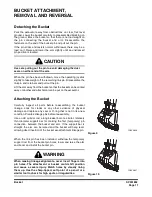
Remove retainers on the end of the mounting pin for the arm
cylinder rod end. Use the assist crane to relieve the weight load
and withdraw the pin. Lower the arm down to the blocking
support for any continued disassembly procedures.
Boom Removal Procedure
NOTE:
Boom removal may be simplified if the shell of the
operator's cabin is taken off the turntable deck first.
Refer to the Operator's Cabin Removal procedure
before continuing, if both components are to be
removed from the excavator.
After the bucket, arm and arm cylinder have been removed,
lower the end of the boom to a stable, secure blocking support.
Attach the assist crane sling to the body of either boom cylinder,
break the mounting pin connection to the boom by tapping
through the pin from the same side of the boom and repeat for
the opposite cylinder.
Release hydraulic pressure and disconnect line couplings as
previously outlined in the Arm Removal Procedure, observing
the same precautions.
Disconnect wiring for work light assemblies and any other
accessory lines or connections. Locate the sling of the assist
crane near the center of gravity, optimum lift point for the boom,
and use the crane to take pressure off the boom foot pin. Drive
out the pin after disassembling retainers and carefully lift away
the boom.
To maintain stability, the counterweight should be removed
whenever the front attachment is taken off the machine.
CAUTION
To make sure that the polished surfaces of cylinder rod
ends will not suffer accidental damage during disassembly
or removal procedures, wrap exposed rod surfaces
(especially those of boom cylinders) with a protective
covering material. Immediately following disassembly and
removal, cylinder rods should always be fully retracted.
This eases handling problems and also avoids possible
damage.
WARNING
Traveling the excavator, swinging the turntable or
movement over bumps or sloping, uneven surfaces could
all produce loss of control and possible accidents or
injuries, if the turntable deck has been unbalanced by
removal of weight from one end only.
Summary of Contents for 5001
Page 2: ......
Page 4: ......
Page 7: ...1Safety ...
Page 8: ......
Page 10: ...SP002025 Track Excavator Safety Page 2 MEMO ...
Page 12: ...SP002025 Track Excavator Safety Page 4 MEMO ...
Page 51: ...1Specifications ...
Page 52: ......
Page 54: ...SP002026 Specification for DX300LCA Page 2 MEMO ...
Page 56: ...SP002026 Specification for DX300LCA Page 4 MEMO ...
Page 58: ...SP002026 Specification for DX300LCA Page 6 ...
Page 63: ...SP002026 Page 11 Specification for DX300LCA ...
Page 78: ...SP002026 Specification for DX300LCA Page 26 ...
Page 79: ...1General Maintenance ...
Page 80: ......
Page 82: ...General Maintenance Procedures SP000016 Page 2 MEMO ...
Page 84: ...General Maintenance Procedures SP000016 Page 4 MEMO ...
Page 100: ...SP000016 General Maintenance Procedures Page 20 ...
Page 101: ...SP000813 Page 1 Standard Torques SP000813 STANDARD TORQUESSP000813 Standard Torques Edition 1 ...
Page 102: ...SP000813 Standard Torques Page 2 MEMO ...
Page 104: ...SP000813 Standard Torques Page 4 MEMO ...
Page 117: ...1Upper Structure ...
Page 118: ......
Page 119: ...SP001737 Page 1 Cabin SP001737 CABIN SP001737 Cabin Edition 1 ...
Page 120: ...SP001737 Cabin Page 2 MEMO ...
Page 122: ...SP001737 Cabin Page 4 MEMO ...
Page 131: ...SP001748 Page 1 Counterweight SP001748 COUNTERWEIGHT SP001748 Counterweight Edition 1 ...
Page 132: ...SP001748 Counterweight Page 2 MEMO ...
Page 134: ...SP001748 Counterweight Page 4 MEMO ...
Page 140: ...SP001748 Counterweight Page 10 ...
Page 141: ...SP002027 Page 1 Fuel Tank SP002027 FUEL TANK SP002027 Fuel Tank Edition 1 ...
Page 142: ...SP002027 Fuel Tank Page 2 MEMO ...
Page 144: ...SP002027 Fuel Tank Page 4 MEMO ...
Page 156: ...SP002027 Fuel Tank Page 16 ...
Page 158: ...SP000021 Fuel Transfer Pump Opt Page 2 MEMO ...
Page 160: ...SP000021 Fuel Transfer Pump Opt Page 4 MEMO ...
Page 165: ...SP001856 Page 1 Swing Bearing SP001856 SWING BEARING SP001856 Swing Bearing Edition 1 ...
Page 166: ...SP001856 Swing Bearing Page 2 MEMO ...
Page 168: ...SP001856 Swing Bearing Page 4 MEMO ...
Page 174: ...SP001856 Swing Bearing Page 10 ...
Page 176: ...SP002028 Swing Reduction Gear Page 2 MEMO ...
Page 178: ...SP002028 Swing Reduction Gear Page 4 MEMO ...
Page 180: ...SP002028 Swing Reduction Gear Page 6 ...
Page 188: ...SP002028 Swing Reduction Gear Page 14 5 Remove No 1 carrier Figure 10 Figure 11 Figure 12 ...
Page 217: ...SP002028 Page 43 Swing Reduction Gear FG000957 Figure 112 FG000958 Figure 113 ...
Page 224: ...SP002028 Swing Reduction Gear Page 50 ...
Page 225: ...1Lower Structure and Chassis ...
Page 226: ......
Page 227: ...SP001741 Page 1 Track Assembly SP001741 TRACK ASSEMBLY SP001741 Track Assembly Edition 1 ...
Page 228: ...SP001741 Track Assembly Page 2 MEMO ...
Page 230: ...SP001741 Track Assembly Page 4 MEMO ...
Page 236: ...SP001741 Track Assembly Page 10 Track Shoe 8 7 2 10 11 9 FG003910 1 3 6 4 5 Figure 4 ...
Page 243: ...SP001741 Page 17 Track Assembly ...
Page 257: ...1Engine and Drive Train ...
Page 258: ......
Page 260: ...SP002029 Drive Coupling Main Pump Page 2 MEMO ...
Page 262: ...SP002029 Drive Coupling Main Pump Page 4 MEMO ...
Page 269: ...1Hydraulics ...
Page 270: ......
Page 272: ...SP001751 Hydraulic System Troubleshooting Testing and Adjustment Page 2 MEMO ...
Page 304: ...SP001751 Hydraulic System Troubleshooting Testing and Adjustment Page 34 ...
Page 305: ...SP000028 Page 1 Accumulator SP000028 ACCUMULATOR SP000028 Accumulator Edition 1 ...
Page 306: ...SP000028 Accumulator Page 2 MEMO ...
Page 308: ...SP000028 Accumulator Page 4 MEMO ...
Page 314: ...SP001620 Center Joint Swivel Page 2 MEMO ...
Page 316: ...SP001620 Center Joint Swivel Page 4 MEMO ...
Page 326: ...SP001620 Center Joint Swivel Page 14 ...
Page 327: ...SP000030 Page 1 Cylinders SP000030 CYLINDERS SP000030 Cylinders Edition 1 ...
Page 328: ...SP000030 Cylinders Page 2 MEMO ...
Page 330: ...SP000030 Cylinders Page 4 MEMO ...
Page 356: ...SP000030 Cylinders Page 30 ...
Page 357: ...SP000031 Page 1 Swing Motor SP000031 SWING MOTOR SP000031 Swing Motor Edition 1 ...
Page 358: ...SP000031 Swing Motor Page 2 MEMO ...
Page 360: ...SP000031 Swing Motor Page 4 MEMO ...
Page 394: ...SP000031 Swing Motor Page 38 FG000756 Figure 93 FG000757 Figure 94 ...
Page 395: ...SP000032 Page 1 Travel Motor SP000032 TRAVEL MOTOR SP000032 Travel Motor Edition 1 ...
Page 396: ...SP000032 Travel Motor Page 2 MEMO ...
Page 398: ...SP000032 Travel Motor Page 4 MEMO ...
Page 400: ...SP000032 Travel Motor Page 6 ...
Page 438: ...SP000032 Travel Motor Page 44 ...
Page 440: ...SP000068 Axial Piston Pump Page 2 MEMO ...
Page 464: ...SP000068 Axial Piston Pump Page 26 Parts List Figure 24 ...
Page 484: ...SP000068 Axial Piston Pump Page 46 ...
Page 485: ...SP000033 Page 1 Gear Pump SP000033 GEAR PUMP SP000033 Gear Pump Edition 1 ...
Page 486: ...SP000033 Gear Pump Page 2 MEMO ...
Page 488: ...SP000033 Gear Pump Page 4 MEMO ...
Page 502: ...SP000033 Gear Pump Page 18 ...
Page 504: ...SP000034 Main Control Valve Page 2 MEMO ...
Page 506: ...SP000034 Main Control Valve Page 4 MEMO ...
Page 513: ...SP000034 Page 11 Main Control Valve ...
Page 539: ...SP000034 Page 37 Main Control Valve ...
Page 572: ...SP000069 Remote Control Valve Work Lever Joystick Page 2 MEMO ...
Page 574: ...SP000069 Remote Control Valve Work Lever Joystick Page 4 MEMO ...
Page 576: ...SP000069 Remote Control Valve Work Lever Joystick Page 6 ...
Page 594: ...SP001743 Travel Control Valve With Damper Page 2 MEMO ...
Page 596: ...SP001743 Travel Control Valve With Damper Page 4 MEMO ...
Page 602: ...SP001743 Travel Control Valve With Damper Page 10 ...
Page 620: ...SP001622 Solenoid Valve Assembly Page 2 MEMO ...
Page 622: ...SP001622 Solenoid Valve Assembly Page 4 MEMO ...
Page 630: ...SP001622 Solenoid Valve Assembly Page 12 Solenoid Valve Diagram Figure 3 ...
Page 636: ...SP001622 Solenoid Valve Assembly Page 18 ...
Page 638: ...SP000192 Breaker EPPR Valve Opt Page 2 MEMO ...
Page 640: ...SP000192 Breaker EPPR Valve Opt Page 4 MEMO ...
Page 650: ...SP001752 Hydraulic Schematic DX300LC DX300LCA Page 2 MEMO ...
Page 652: ...SP001752 Hydraulic Schematic DX300LC DX300LCA Page 4 MEMO ...
Page 654: ...SP001752 Hydraulic Schematic DX300LC DX300LCA Page 6 ...
Page 656: ......
Page 657: ...1Electrical System ...
Page 658: ......
Page 660: ...SP002030 Electrical System Page 2 MEMO ...
Page 663: ...SP002030 Electrical System Page 5 MEMO ...
Page 774: ...SP002031 Electrical Schematic DX300LCA Page 2 MEMO ...
Page 776: ...SP002031 Electrical Schematic DX300LCA Page 4 MEMO ...
Page 778: ...SP002031 Electrical Schematic DX300LCA Page 6 ...
Page 780: ......
Page 781: ...1Attachments ...
Page 782: ......
Page 783: ...SP001851 Page 1 Boom and Arm SP001851 BOOM AND ARM SP001851 Boom and Arm Edition 1 ...
Page 784: ...SP001851 Boom and Arm Page 2 MEMO ...
Page 786: ...SP001851 Boom and Arm Page 4 MEMO ...
Page 798: ...SP001851 Boom and Arm Page 16 ...
Page 799: ...SP001852 Page 1 Bucket SP001852 BUCKET SP001852 1Bucket Edition 1 ...
Page 800: ...SP001852 Bucket Page 2 MEMO ...
Page 802: ...SP001852 Bucket Page 4 MEMO ...


