VPRS-4175E OPERATION MANUAL
Issue : 2009.03
ED : 1
VPRS-4175E OPERATION MANUAL 24 /31
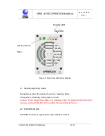
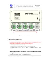
4.3 STB LED
The rectifier module is in standby mode, and does not feed output.
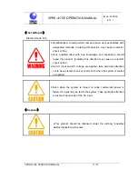
Caution: Even though the STB LED is turned on (yellow), AC power will be fed to
the module.
☞
While AC power is input, rectifier unit turns on POWER ON LED. When
communication with the control panel is failed or when rectifier module output OC
alarm (OCA) is driven, STB LED (yellow) and POWER ON LED are turned on
simultaneously.
4.4 ALARM LED
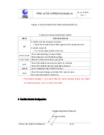
In one of the following conditions, ALARM LED(RED) will be turned on:
* When AC power excceds UV/OV limits (UV limit : 90V, OV limit: 280V);
* When the module is shut down due to output OV protection circuit driving;
* When the module is shut down due to internal high temperature protection circuit
driving;
* When the voltage falls below UV limit due to current limit circuit driving;
* When internal fan is failed;
* When the module is shut down due to an external signal (Green, yellow and red
LEDs are blinking.)
* When output is not made due to other problems, or when the voltage falls below
UV limit.
4.5
ADJUSTMENT VR
This function enables to calibrate output voltage of the rectifier module. Turn the


