background image

4. 1 How to set values 

20 

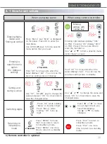
When using key panel 

When using remote controller 

Entering Menu 

mode and 

finding an option 

Entering a 

specific menu 

option 

(Ex: Address 

setting) 

Setting and 

saving a value 

Switching digits 

Returning to 

initial Menu 

mode 

Entering 

address with 

number key 

Press “Menu” key: “MnU” is displayed 
on the panel. Press OK to enter the 
main Menu. 
Use UP DOWN keys to find a specific 
menu option that you need. 

2 Seconds 

Hold “OK” for 2 seconds when the 
panel displays “Adr”. You can see the 
previous setting value on display.


Use “UP”, “DOWN” keys to change the 
value and press “OK” for 2 seconds to 
save the changed value.


,Press “OK” while holding 
“Menu” to be down digit. 
Press “Menu” while 
holding “OK” to be up 
digit . 

Entering right address display “SEL” 
on FND. Pressing “OK” display “MnU” 
on FND. Press OK one more time to 
enter the main Menu. 
Use “▲” or“▼” to find a specific menu 
option that you need.


or 

Hold “OK” for 2 seconds when the 
panel displays “Adr”. You can see the 
previous setting value on display.


Use “▲” or“▼” to change the value and 
press “OK” for 2 seconds to save the 
changed value. 

or 

Press“◀” or ”▶” to move 
to next digit. Check you 
have FND blinking. 
Use“▲” or“▼” to make 
changes. 

or 

Press “MENU” for more 
than 2 seconds to return 
to initial Menu mode. 
Press “MENU” one more 
time to return to a standby 
mode. 

Press “ESC” to return to 
initial Menu mode. 
Press “ESC” one more 
time to return to a standby 
mode. 

DONG IL TECHNOLOGY LTD 

and 

1) Remote controller is optional. 

2 Seconds 

2 Seconds 

Summary of Contents for AMF-AE Series

Page 1: ...e product in order to achieve maximum performance Keep this instruction manual within your reach after reading so that it can be used at any time ION BLOWER AMF AE Series 28 Namyang ro 930beon gil Hwaseong si Gyeonggi do Korea Tel 82 31 299 5453 Fax 82 31 357 2610 ...

Page 2: ... 2 2 Wiring diagram 2 3 Cautions 3 Cautions Maintenance 12Page 3 1 Cautions for operation 3 2 Cleaning replacement of ion emitters 4 Settings 15Page 4 1 How to set values 4 2 Explanation on Menu options APPENDIX 17Page 1 Trouble shooting 2 Warranty Before installation be sure to read carefully at least 1 7 Cautions 2 Installation Connection parts 2 DONG IL TECHNOLOGY LTD CONTENTS ...

Page 3: ...t current AC Max 0 61A Max 1 22A Max 1 83A Input current DC Max 1 5A X X Ion generating method Pulsed AC Output Frequency 10Hz 50Hz adjustable Ion emitter pin Tungsten Ion balance 30V Typical Decay time Better than 2 0 seconds at 600mm Fan Speed Max Level 5 Air volume Max 6 4 min per Fan Ozone generation Under 0 005ppm Display 7segment Display High Voltage Alarm LED G R Fan Alarm LED G R Green Nor...

Page 4: ...egory Code Length mm Remarks Controller A 54 6 Fan Module B 170 0 Space Box C 56 6 Side Cover D 18 6 Bracket Ass y E 9 6 Height F 217 8 Width G 106 1 Bracket Height H 173 6 Bracket Width I 97 5 Bracket Depth J 68 0 Blower Length L 262 Min Length ...

Page 5: ...emarks Controller A 54 6 Fan Module B 170 0 Space Box C 56 6 Side Cover D 18 6 Bracket Ass y E 9 6 Height F 217 8 Width G 106 1 Bracket Height H 173 6 Bracket Width I 97 5 Bracket Depth J 68 0 Blower Length L 432 Min Length 2Fans 602 Min Length 3Fans 1 000 Max Length ...

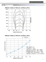
Page 6: ...rformance Relation between Distance and Decay Time Relation between Distance and Decay Time Fan Speed L 5 Frequency 30Hz Measure Condition 1kV 100V Charged plate size 150 x 150 Charged plate Capacitance 20 Ambient conditions 25 45 RH ...

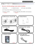
Page 7: ...n Main body Standard brackets AC power cable 1 800 DC Power Cable 1500mm Including ground wire Remote controller RJ45 CABLE 8Pin PLC RS485 Communications Options Options Main body ex 1 Fan 2 Fan DC Power Cable including ground wire AC Power Cable RJ45 CABLE 8Pin PLC RS485 Communications Remote controller options options ...

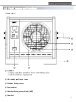
Page 8: ...1 6 Parts names and functions Front side Control Display operation condition menu and setting value Control on off AC input power Air outlet and front cover Emitter fixing cover Ion emitter Bracket fixing wrench bolt M5 Bracket ...

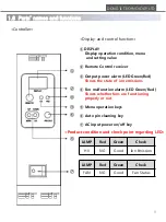
Page 9: ...ondition menu and setting value Remote Control receiver Output power alarm LED Green Red Shows the state of ion emissions Fan malfunction alarm LED Green Red Shows whether fans are functioning properly or not Menu operation keys Auto pin cleaning key AC input power on off key LAMP Red Green Check FAN NG Good Fan Status Product condition and check point regarding LED ...

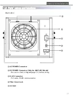
Page 10: ...D 1 6 Parts names and functions Back side AC POWER Connector DC POWER Connector Only for AMF AE1 Model Be sure to check a diagram page 13 before wiring RJ 45 Connector PLC cable RS485 communication Filter Cover Lock Air inlet ...

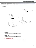
Page 11: ...TD 1 6 Parts names and functions Bracket Tilt hole Use this hole if you need to adjust angle Height hole Use this hole if you need to adjust height Main body fixing hole Fix a main body to installation place before operation ...

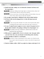
Page 12: ...ect ground cable using a provided DC24V power cable No grounding may cause a malfunction In case of using DC power supply be sure to connect the ground wire in DC24V cable included in the package referring the wiring diagram 2 2 The product must be connected to prevent electric shock and guarantee best performance When power is supplied LED is lit on in red and is turn into green within a second F...

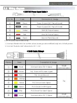
Page 13: ...munication TX Signal RS485 Communication RJ45 Cable Wiring DONG IL TECHNOLOGY LTD 2 2 Wiring diagram PIN No Color Connection Usage Black Power Ground DC Power Ground White Power Ground DC Power Ground Yellow 24V DC Power Supply Red 24V DC Power Supply Black Ground Field Ground 24V DC Power Input Cable 24V DC power input cable wiring 1 Connect Black short wire White wire to power ground and Black l...

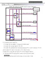
Page 14: ...V which makes PLC work If you open it PLC doesn t work Please refer to the AMF AE Series PLC Circuit Diagram above The brown HVPS and blue Fan cables are for an alarm signal Setting Load Set the output current under 100mA DONG IL TECHNOLOGY LTD PLC On off S W 1 2 7 Blue Fan Alarm Signal 6 Green PLC On off Signal LOAD PLC CLEAN S W 4 Orange PLC P상 DC 24V 5 Yellow PLC Clean Signal 2 Brown HVPS Alarm...

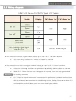
Page 15: ...hile PLC Clean Switch on a diagram is closed ions are not generated for safety reasons R C filter on input terminal is connected in parallel to prevent malfunction due to external environment or chattering noise Keep close more than 0 5 seconds the switch when you use non lock type switch DONG IL TECHNOLOGY LTD Switch Display PLC Alarm nc PLC Alarm no Ion on Close I_o Low High Open Ion off Close P...

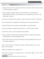
Page 16: ...ormed of this instruction before installing or using the product Don t put extraneous materials like metal wire etc near the product for safety Don t move clean or touch the product during operation Remove water and oil from the place where the product is installed and avoid high temperature 50 and high humidity RH 70 Don t use this product in the place influenced by strong magnetic field It may c...

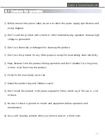
Page 17: ... this product for any other purpose except for neutralizing static electricity Keep distance from the product during operation and don t breathe for a long time in front of air flow from the product Firmly fix the main body not to fall Install the product beyond children s reach Don t install the product in the place exposed to flame direct ray of the sun or a lot of dusts Be sure to check a groun...

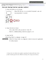
Page 18: ...pin cleaning function operation method Using the button on a front side When PIN CLN key on a controller be pressed auto pin cleaning function is started Using the timer on menu Set a value which cycle you want on menu tiP Refer to a detailed setting method on page 4 1 4 2 Using the PLC After wiring Refer to a diagram on page 3 2 While PLC Clean Switch on a diagram is closed ions are not generated...

Page 19: ...lean the ion emitters with cotton swab with alcohol and assemble it in reverse order Be cautious not to touch the emitter pin with a finger to prevent finger prints For cleaning a fan cover use soft clothes or tissues Handle emitter pins with care not to be hurt by the sharp point Replace emitter pins if emitter pins are damaged Assemble it in reverse order How to replace emitter pin Do step in ma...

Page 20: ...ess OK while holding Menu to be down digit Press Menu while holding OK to be up digit Entering right address display SEL on FND Pressing OK display MnU on FND Press OK one more time to enter the main Menu Use or to find a specific menu option that you need or Hold OK for 2 seconds when the panel displays Adr You can see the previous setting value on display Use or to change the value and press OK ...

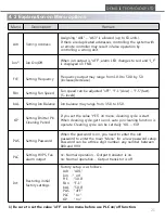
Page 21: ...e from 35 0 to 65 0 tIP Setting Emitter Pin Cleaning Period If you set the value YES on menu cleaning cycle is start When cleaning cycle get to end auto pin cleaning function is operate Cleaning cycle can be set daily t01 t30 PAS Setting Password When the password is on you need to enter the old password to enter the main Menu for a new password setup Password can be a three digit number any numbe...

Page 22: ... red 5 sec later after power connection please contact your dealer Auto pin cleaning function doesn t work Please contact your dealer Fan doesn t work on power Check the value oFF on Ion menu Check the value oFF on Fan menu Fan LED is red and the fan doesn t work Please contact your dealer When you smell something metallic It is natural smell generated when making high voltage When you smell somet...

Page 23: ...f the product is used in a way different from that is explained in this manual or remade by users arbitrarily 2 Any damage led by improper usage We recommend the installation circumstances in this manual but that is just a recommendation and users are responsible for understanding the product s specification and judgment of suitability of usage 3 Direct or indirect damage led by the product malfun...

Reviews: