FAULT FINDING AND REPAIR
20509 Issue 7 Jan 2018
4-31
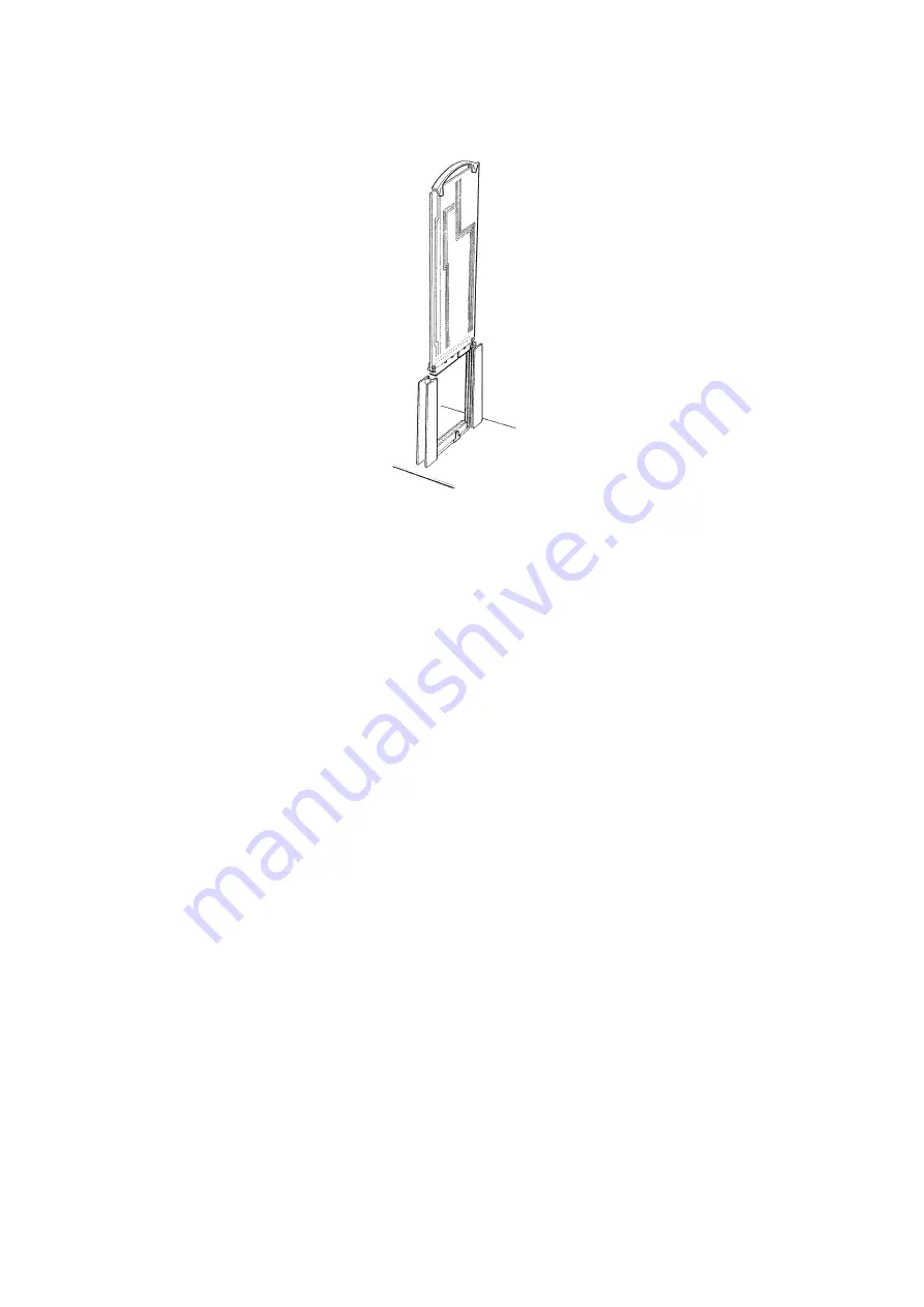
(2) Each PCB is fitted into a socket on the motherboard. To remove a
PCB, pull on the handle at the top after removing any cabinet wiring
connectors. The PCB sockets and connectors are polarised and
must be refitted into their correct positions.
(3) When refitting a PCB, inspect its connector and the motherboard
socket to check for damage. Be sure to seat the PCB correctly into
its connector and guides.
(4) The printer must be shut down and the power removed. Before fitting
any replacement PCB, make sure that any links or components
containing software are correct. To avoid damage make sure that the
correct PCB is being fitted and that it is the right way round before
inserting. PCB insulation panels must be fitted to replacement PCBs.
Replacing the Universal Serial Interface PCB
The printer must be shut down, the power removed and the cabinet cover
removed.
If the replacement PCB is not fitted with the software PROM Integrated
Circuits (IC7, IC10 and IC9), these must be transferred from the old PCB to
the new PCB. It is vital that each IC is transferred into the identical position,
has pin1 in the correct position and no pins are bent or damaged. It is also
essential that antistatic precautionary procedures are also used.
This PCB has links and switches that must be set correctly. The usual
positions are shown in the diagrams when using:
• the white pocket terminal with the large display window (see T64
Terminal User's Pocketbook) or
• the blue pocket terminal with the small display window.
TP3466-1
Summary of Contents for Macrojet 2
Page 1: ...Domino Macrojet 2 Product Manual ...
Page 2: ... 2 20509 Issue 7 Jan 2018 THIS PAGE INTENTIONALLY LEFT BLANK ...
Page 5: ...20509 Issue 7 Jan 2018 5 ...
Page 10: ...HEALTH AND SAFETY 1 2 20509 Issue 7 Jan 2018 THIS PAGE INTENTIONALLY LEFT BLANK ...
Page 14: ...HEALTH AND SAFETY 1 6 20509 Issue 7 Jan 2018 THIS PAGE INTENTIONALLY LEFT BLANK ...
Page 16: ...DESCRIPTION 2 2 20509 Issue 7 Jan 2018 This page intentionally left blank ...
Page 38: ...DESCRIPTION 2 24 20509 Issue 7 Jan 2018 THIS PAGE INTENTIONALLY LEFT BLANK ...
Page 40: ...MAINTENANCE PROCEDURES 3 2 20509 Issue 7 Jan 2018 THIS PAGE INTENTIONALLY LEFT BLANK ...
Page 52: ...MAINTENANCE PROCEDURES 3 14 20509 Issue 7 Jan 2018 THIS PAGE INTENTIONALLY LEFT BLANK ...
Page 66: ...FAULT FINDING AND REPAIR 4 14 20509 Issue 7 Jan 2018 Solenoid Connections ...
Page 94: ...INSTALLATION A 2 20509 Issue 7 Jan 2018 THIS PAGE INTENTIONALLY LEFT BLANK ...
Page 114: ...INSTALLATION A 22 20509 Issue 7 Jan 2018 THIS PAGE INTENTIONALLY LEFT BLANK ...


