background image

25

Electrical installation

Electrical installation may only be carried out by qualified personnel.

The connection cables must be laid in such a way that they do not come

in contact with hot components of the unit/burner or with sharp edges.

The electrical installation must comply with national regulations 

(EN 60335-2-24, EN 1648-1, EN 1648-2 for Europe).

It is advisable to run the incoming supply through an on-board fuse or

automatic circuit breaker. The power cable must be laid in such a way

that it does not come in contact with hot components of the unit/burner

or with sharp edges.
Changes at the internal electrical installation or the connection of other

electrical components (e.g. additional fan) to the internal wiring of the

appliance will expire the e1/ CE admittance as well as any claims from

guarantee and product liability!

Power line connection

The power must be supplied via a properly earthed socket outlet or hard-

wired connection.

Where a socket outlet is used for the mains connection lead, the outlet

must be freely accessible.

It is advisable to run the incoming supply through an on-board fuse or automatic

circuit breaker. 

The power cable must be laid in such a way that it does not come in contact with hot

components of the unit/burner or with sharp edges.

If the connection cable is damaged it must be replaced by the Customer

Service at Dometic, or by respectively qualified personnel, in order to

prevent any hazards.

Battery connection

The machine's mains 12V connection cable is connected (observing correct 

polarity) to a terminal strip. The cabling must be direct and by the shortest possible 

route to the battery and alternator respectively (motorcaravan). 

The 12V circuit must be protected with a 16A fuse.

The heating element circuit must be connected to the vehicle battery by a suitable   

ignition operated relay in order that the 12V supply is only live while the vehicle 

ignition is switched on.

The connection C/D (interior light, electronics ; cable black / violet) must be 

permanently attached,

and must not be cut-out when the vehicle ignition key is 

turned off.  This can be realised with an on-board habitation battery .

For 12V operation any habitation isolation relay must be by-passed.

6.9

6.9.1

6.9.2

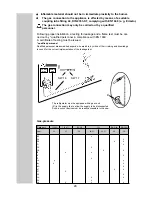
6  mm²

< 6 m

10 mm²

> 6 m

min 2,5 mm²

(EN1648-1)

Cross-sectional area of cable

Length of cable

Motorcaravan

Caravan (

inside

)

Caravan (

outside

)

2,5mm²

Summary of Contents for TYPE C40 RM 7601 L

Page 1: ...NUAL ABSORPTION REFRIGERATOR for CARAVAN and MOTORHOME EN English OPERATING INSTRUCTIONS INSTALLATION INSTRUCTIONS RM 7601 L RM 7605 L RM 7651 L RM 7655 L Model number Product number Serial number Ple...

Page 2: ...conditions the refrigerator cannot guarantee having the temperature needed for food that perishes quickly Foods that perish quickly include all the products with a stipulated use by date and a minimu...

Page 3: ...panel 13 5 12 Changing the doorhang 14 5 13 Troubleshooting 15 5 14 Maintenance 16 5 15 Product liability 16 5 16 Environmental hints 16 5 17 Disposal 16 5 18 Energy saving tips 16 5 19 Technical dat...

Page 4: ...cylinder open the windows and leave the room do not switch on anything electrical extinguish naked flames Never open the cooling unit it is under high pressure Work on the gas flue system and electri...

Page 5: ...ata plate inside the refrigerator Damage in transit After removing the packaging check whether the refrigerator has been damaged during transportation Any damage sustained in transit must be reported...

Page 6: ...is selected by means of energy selector switch A Energy selector switch A has four settings AC mains power DC 12V Gas liquid gas OFF Appliances with automatic energy selection have the additional sett...

Page 7: ...emperature in the main refrige rator compartment A 1 Set energy selector switch A to 12V Operating display C 12V lights green Appliance is in function 2 Use rotary switch B to regulate the temperature...

Page 8: ...gnition the display LED C Gas lights yellow The refrigerator is in function Use rotary switch B to regulate the temperature in the main refrigerator compartment AUTO operation RM7XX5 L models are equi...

Page 9: ...for 15 mins During this time the appliance is in stand by operation mode and only the AUTO LED lights up The use of naked flames is prohibited in petrol station environments If the refuelling stop las...

Page 10: ...ting 12VDC 3 5W around the freezer compartment During summer months with high temperatures and humidity the metal frame may have water droplets forming To evapo rate these droplets switch on the frame...

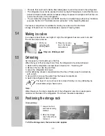
Page 11: ...the back of the refrigerator From there the water evaporates Positioning the storage rack 5 5 5 6 1 Fill the ice cube tray with drinking water 2 Place the ice cube tray in the freezer compartment 5 4...

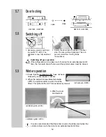
Page 12: ...1 Set energy selector switch A to position 0 OFF The appliance is now fully switched off 2 Secure the door open by means of the door stop The door will be slightly ajar This is to prevent mould from f...

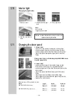
Page 13: ...es for replacement light bulbs 1 Upper door remove the two screws holding the control panel unsrcew upper hinge pin A and remove the door unscrew upper part of the door frame and the panel insert new...

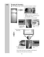
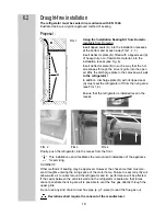
Page 14: ...A screw and keep it to hand 2 Take off the door by moving it upwards 3 Unscrew middle hinge and remove lower door 4 Remove the middle hinge 7 Affix the middle hinge 6 Positon the hinge at the opposit...

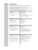
Page 15: ...230V Possible cause Action you can take a On board fuse defective b No connection to supply voltage c AES gas operation despite connection to the supply voltage a Fit new fuse b Establish power connec...

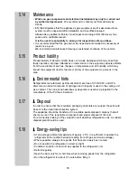
Page 16: ...nts Refrigerators manufactured by Dometic GmbH are free of CFC HCFC and HFC Ammonia a natural compound of hydrogen and nitrogen is used in the cooling unit as a coolant The non ozone hazardous cyclope...

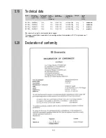
Page 17: ...05 L 1245x525x543 142 lit 25 lit 200 W 170 W ca 3 2 KWh 380 g 42 kg X standard door RM 7651 L 1245x525x570 150 lit 26 lit 200 W 170 W ca 3 2 KWh 380 g 43 kg X curved door RM 7655 L 1245x525x570 150 li...

Page 18: ...l regulations EN 60335 1 EN 60335 2 24 EN 1648 1 EN 1648 2 The gas installation must comply with national regulations Technical regulations EN 1949 Technical regulations EN 732 Local and building cont...

Page 19: ...e refrigerator off from the living area see FIG 1 4 Ensure that the refrigerator is installed level in the recess Finally push the refrigerator into the recess from the front This installation option...

Page 20: ...walls of the ventilation shaft should be local to avoid the build up of condensation and drafts The parts of the shaft walls which are situated above and next to the exhaust for the combus tion gases...

Page 21: ...tall the ventilation grilles cut two rectangles 451mm x 341mm in the outer wall of the vehicle for position of the cuts see point 6 3 L 500 To install the ventilation grilles cut a rectangle 451mm x 1...

Page 22: ...there are four plastic sleeves with screws for securing the refrigerator The sidewalls or rails attached for securing the refrigerator must be designed in such a way that the screws will remain firmly...

Page 23: ...iance The operating pressure corresponds to the standard pressure of the country of specification EN 1949 EN 732 Only one connection pressure is permissible for any one vehicle A plate showing the per...

Page 24: ...P 30 mbar 30 37 50 28 37 30 37 50 30 Gas pressure Following proper installation a testing for leakage and a flame test must be car ried out by qualified personnel in compliance with EN 1949 A certifi...

Page 25: ...supply through an on board fuse or automatic circuit breaker The power cable must be laid in such a way that it does not come in contact with hot components of the unit burner or with sharp edges If...

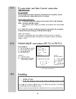
Page 26: ...urrent flows via the D and S connection therefore no particularly large cross section is required for these connections approx 1mm Terminal strip DC connections RM 76x1 and RM 76x5 Retrofitting Connec...

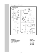
Page 27: ...lett violet braun brown weiss white gr n green gelb yellow rot red A B C D permanently connection DC Burner Control Device ignition unit Ground terminal block heating element DC Gas Valve temp sensor...

Page 28: ...braun brown weiss white gr n green gelb yellow rot red A B C D permanently connection DC Burner Control Device ignition unit Ground terminal block heating element DC Gas Valve temp sensor heating ele...

Page 29: ...29...

Page 30: ...Dometic GmbH In der Steinwiese 16 D 57074 Siegen www dometic de caravan www dometic com...

Reviews: