background image

EN

RMDX21, RMDX25

Installing the refrigerator

23

z

If the minimum distance between the air inlet and outlet vents cannot be 
met, a roof vent must be installed instead of the air outlet vent.
– The roof vent should be installed directly above the back of the 

refrigerator as far as this is possible. Use an air duct (fig.

5

1, page 4) 

if you need to install the roof vent offset, otherwise heat will accumu-
late there.

– The distance between the air inlet vent and the roof vent must be at 

least 1400 mm (fig.

5

, page 4).

– If a roof air conditioner is provided, the distance between the roof vent 

(fig.

6

1, page 4) and the air outlet of the roof air conditioner 

(fig.

6

2, page 4) must be at least 300 mm.

z

The refrigerator must not be installed at the side of the air inlet and 
outlet vents as this leads to poor performance and increases the power 
consumption of the refrigerator.

z

The air inlet and outlet vents must not be covered by vehicle parts (such 
as an open door or by installing accessories such as bicycle racks) while 
operating.

z

A separate flue duct must be installed under the air outlet vent, see chap-
ter “Installing the flue duct” on page 27.

z

Install the refrigerator so that it is protected from excessive heat, as this 
leads to poor performance and increases the power consumption of the 
refrigerator.

z

The electrical installation must comply with national and local regulations.

z

The gas installation must comply with national and local regulations.
AS 5601.2 – Gas Installations
NZ 5601 – Gas Appliance Safety

z

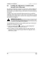
The refrigerator must be installed in a draught-proof location, see chapter 
“Installing the refrigerator in a sealed location separate to the living space” 
on page 24.

Summary of Contents for RMDX21

Page 1: ...Absorber refrigerator Installation Manual EN RMDX21 RMDX25...

Page 2: ...RMDX21 RMDX25 2 622 mm 525 mm 1245 mm 550 mm 1264 mm B A 1 2 3 4 1 2...

Page 3: ...RMDX21 RMDX25 3 1250 1250 1 3 10 40 40 40 4...

Page 4: ...RMDX21 RMDX25 4 1400 10 40 1 5 300 1 2 6...

Page 5: ...RMDX21 RMDX25 5 40 mm 8 1 7 3 2 1 9 0 a...

Page 6: ...RMDX21 RMDX25 6 1 2 3 b 1 2 c d e f...

Page 7: ...RMDX21 RMDX25 7 10 1 9 7 8 6 6 4 5 3 2 g 1 2 h min 15 mm 1 2 3 i...

Page 8: ...RMDX21 RMDX25 8 j 1 2 k l 507 5 907 4 1 7 1 7 1 7 507 5 99 5 300 36 99 5 507 5 300 36 A B...

Page 9: ...RMDX21 RMDX25 9 1 2 3 4 m...

Page 10: ...RMDX21 RMDX25 10 4 3 2 1 n...

Page 11: ...RMDX21 RMDX25 11 1 2 3 o...

Page 12: ...RMDX21 RMDX25 12 3 1 2 p q...

Page 13: ...RMDX21 RMDX25 13 2 3 1 r s...

Page 14: ...RMDX21 RMDX25 14 IN OUT L L N N AC TO GV 12VDCOUT TO FC TOP ABS HE OUT 12 VDC HE IN sw rt br br br ws ws ws S D D vt sw rt vt rt L N L A B C D E G F 1 2 6 5 4 8 7 9 16 10 3 12 13 11 N 14 15 t...

Page 15: ...wer supply 11 Gas inlet 12 Gas outlet 13 Gas valve 14 DC power outlet 15 Gas valve supply line 16 Switch off fuse overheating protection A Optional connections to DC power outlet B Negative terminal D...

Page 16: ...commended size AES Refrigerator DC connections D Control Element DC D C B E F v Vehicle Anderson plug must be controlled by ignition relay House Battery Anderson Plug Anderson cables must be the recom...

Page 17: ...C B E F x Fridge Switch Vehicle Anderson plug must be controlled by ignition relay House Battery Anderson Plug Anderson cables must be the recommended size AES Refrigerator DC connections D Control El...

Page 18: ...ies 21 5 Intended use 21 6 Installing the refrigerator 22 7 Connecting the refrigerator 30 8 Technical data 35 1 Explanation of symbols A I NOTE You can find details on the operation in the operation...

Page 19: ...rigerator if it is visibly damaged z If the AC power cable for this refrigerator is damaged it must be replaced by the manufacturer customer service or a similarly qualified person in order to prevent...

Page 20: ...z Do not install the refrigerator near naked flames or other heat sources heaters direct sunlight gas ovens etc z Danger of overheating Always ensure sufficient ventilation so that the heat generated...

Page 21: ...any questions please contact the dealer or your service partner directly 5 Intended use The refrigerators RMDX21 and RMDX25 are designed for installation in caravans or motorhomes They are only suitab...

Page 22: ...that the heat generated can be easily released to the outside Lower air inlet vent LS300 must be installed as flush as possible to the vehicle floor Air inlet vent must have a minimum of 400 cm2 open...

Page 23: ...f the air inlet and outlet vents as this leads to poor performance and increases the power consumption of the refrigerator z The air inlet and outlet vents must not be covered by vehicle parts such as...

Page 24: ...interior of the vehicle The purpose is to provide a seal between the interior of the vehicle and the cooling unit and ventilation area behind the refrigerator The manufacturer recommends using a flexi...

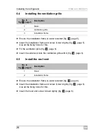
Page 25: ...mm diameter or larger Make an air inlet vent in the floor fig 2 4 page 2 behind the refrigerator near the gas burner Shield the end of the opening with a deflector to prevent sludge or dirt from getti...

Page 26: ...lle fig b page 6 Insert the slider and lock the ventilation grille with it fig b page 6 6 5 Install the roof vent Ensure the installation frame is water resistant fig d page 6 Insert the installation...

Page 27: ...le of 45 towards the rear wall Attach the T piece adaptor and flue pipe with a screw fig g 6 page 7 Install the mounting plate fig i page 7 Fill the opening with fire resistant material e g stone wool...

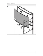
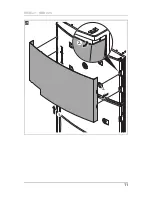
Page 28: ...Refrigerator door B Removing the door panel from framed door model Proceed as follows fig m page 9 Remove the door trim carefully It is only clipped in and held in place by small hooks Pull the old p...

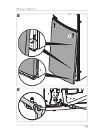
Page 29: ...ows fig o page 11 Push the old panel upwards as far as the stop Pull the old panel out of the door Installing the new door panel on frameless door model Freezer compartment door fig p page 12 Push the...

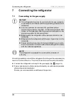
Page 30: ...ator may only be connected to the gas supply by a specialist in accordance with the applicable guidelines and standards z Only use cylinders of universal LPG gas fitted with an approved gas pressure r...

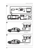
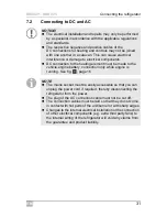
Page 31: ...ment must be made to the vehicle engine battery connection only while engine is running See fig u page 16 NOTE z The mains socket must be easily accessible so that you can unplug the power cord if req...

Page 32: ...ng cartridge DC power 9 LED lighting 10 Electronics DC power supply 11 Gas inlet 12 Gas outlet 13 Gas valve 14 DC power outlet 15 Gas valve supply line 16 Switch off fuse overheating protection A Opti...

Page 33: ...ent battery from completely discharging if the engine is switched off fig u page 16 Connect DC positive heater cable to terminal fig t E page 14 Connect DC negative heater cable to terminal fig t F pa...

Page 34: ...ds for example z B ttner MT 300 S www buettner elektronik de z Votronic MPP 240 Duo Digital www votronic de 7 3 Connecting an AES refrigerator optional See fig v page 16 Connection to suit motor home...

Page 35: ...y via a power diode The D wire can only get a 12 V signal when the battery is being charged House battery recharged by vehicle The D is turned on and off by the vehicle starting and stopping 8 Technic...

Page 36: ...1 Auckland 64 9 622 1490 64 9 622 1573 Mail customerservices dometic co nz NORWAY Dometic Norway AS ster yveien 46 N 3232 Sandefjord 47 33428450 47 33428459 Mail firmapost dometic no POLAND Dometic Po...

Reviews: