background image

6

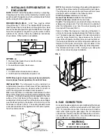
plug.  The free length of the cord is 2 feet and therefore
recommended that the receptacle be located to the right side
of the refrigerator (viewed from the rear) and approximately
6 inches from the floor (see FIG. 7). This allows easy access
through the vent door. The cord should be routed to avoid
direct contact with the burner cover, flue cover or any other
components that could damage the cord insulation.

11. 12 VOLT DC CONNECTION

This refrigerator model is not designed for 12 volt DC
operation of the cooling system; however, 12 volt DC must
be supplied to the refrigerator to operate the controls.  Use
a  minimum of a 14 gauge wire between the battery and
refrigerator to supply the control voltage.  The connection is
made to the positive (+) and negative (-) terminals of the
terminal block on back of refrigerator (See FIG. 6).  The 12
volt DC supply circuit must be fused, and the maximum fuse
size is 5 amps.

DO NOT use the body or chassis of the vehicle as a
substitute for either of the two conductors.  Do not connect
any other electrical equipment of lighting to the refrigerator
circuit.

CAUTION

The 12 volt DC control circuit must be connected directly
to a battery.  Connecting the control circuit to an
unregulated converter can result in improper operation
of the refrigerator.

12. INSTRUCTION FOR

MOUNTING DOOR PANEL

The refrigerator is normally delivered without the door pan-
els. Before starting the mounting work, check that the panel
dimensions are in compliance with those given in the Table
on Page 7 and the instructions are read thoroughly. When
mounting the panel, proceed as follows. (See FIG. 8).
NOTE:  If raised door panels are going to be used, be

1

1

1

2

1

1

6

4

3

5

1

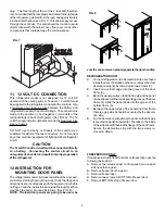
FIG. 8

sure the consumer can properly operate the door handles.

REFRIGERATOR DOOR:
A.

On new refrigerators, the decoration strips are taped
inside the door. If installed on the door, remove the door
decoration strip (2) by removing its two screws (1).

B.

Insert one vertical edge into the groove of the door
frame (3).

C.

Bend the panel gently so that the free side of the panel
can be slipped into the corresponding groove of the door
frame (4). Slide the panel down into the groove of the
bottom frame (5).

D.

Between the upper edge of the panel and door frame
there is a gap which should be covered by the decora-
tion strip.

E.

Put the decoration strip across the door so that the gap
is covered and push it upward (6). The tabs on the inside
of the strip should fit behind the flange of the door frame.
Secure the decoration strip with the two screws re-
moved in Step A.

FREEZER DOOR ONLY:
If the above instructions will not work on freezer door, use the
following instructions:
A. Remove two screws under control panel (one on each

side near the hinges).

B. Remove freezer door hinge pin.
C. Remove freezer door.
D. Remove two screws in BOTTOM of freezer door.
E. Remove BOTTOM strip of freezer door.

FIG. 7

Summary of Contents for RM7030

Page 1: ...WARNING Improper installation adjustment alteration service or maintenance can cause injury or property dam age Refer to this manual For assis tance or additional information consult a qualified installer service agency or the gas supplier AVIS Cet appareil doit être réparé seulement par un réparateur autorisé Modification de l appareil pourrait être extrèmement dangeruse et pourrait causer mal ou...

Page 2: ...owever contingentontheinstal lation being made in accordance with the following instruc tions as applicable In the U S A the installation must conform with 1 National Fuel Gas Code ANSI Z223 1 latest edition 2 ManufacturedHomeConstructionandSafetyStandard Title 24 CFR Part 3280 3 Recreational Vehicles ANSI A119 2 latest edition The unit must be electrically grounded in accordance with the National...

Page 3: ...ator NOTE Clearance N isthedistancebetweenthebottom of the lower vent to the roof material For ventilation height refertoSectionA Installation Item5 Ventilation Heights See FIG 2 FIG 2 e Refrigerator Overall Installation Recess Model Dimensions Dimensions Dimensions RM7030 Height Width Depth Height Width Depth Height Width Depth A B C h w d H W D Inches 58 3 4 33 1 2 23 5 8 57 1 8 32 3 8 22 5 8 57...

Page 4: ...he appliance s combustion system from the vehicle interior NOTE Becarefulnottodamagethesealingstripappliedto theflooroftheenclosurewhentherefrigeratorisputinplace The refrigerator is secured in the enclosure with six screws and they must be installed in the following order First Two Screws installed on front base Second Two Screws installed in the top frame Third Two Screws installed in the rear b...

Page 5: ...le Cover Drain W ater Hose Flexible Cord FIG 6 When testing the gas supply system at test pressures in excess of 1 2 psig the refrigerator and its individual shutoff valve must be disconnected from the gas supply piping system When testing the gas supply system at pressures less than orequalto1 2psig theappliancemustbeisolatedfromthe gas supply piping by closing its individual manual shutoff valve...

Page 6: ... PANEL The refrigerator is normally delivered without the door pan els Before starting the mounting work check that the panel dimensions are in compliance with those given in the Table on Page 7 and the instructions are read thoroughly When mounting the panel proceed as follows See FIG 8 NOTE If raised door panels are going to be used be 1 1 1 2 1 1 6 4 3 5 1 FIG 8 suretheconsumercanproperlyoperat...

Page 7: ...ectionsoftheevaporator tubing This will slow the circulation of hydrogen and ammo nia gas or in severe cases completely block it resulting in a loss of cooling Any time the vehicle is parked for several hours with the refrigerator operating the vehicle should be leveled to pre ventthislossofcooling Thevehicleneedstobeleveledonly so it is comfortable to live in no noticeable sloping of floors or wa...

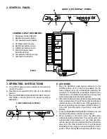
Page 8: ...tor button 2 to the DOWN position If 120 volts AC is available the AC mode indicator lamp A will illuminate indicating AC operation If120voltsACisnotavailable theGASmode indicator lamp C will illuminate and the control system will automatically switch to GAS operation 2 IftheCHECKindicatorlamp D illuminatesandtheGAS mode indicator lamp C is off the controls have failed to ignite the burner in the ...

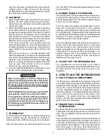
Page 9: ... the frozen food storage compartment provided they are precooled first in the refrigerator They can be stored about three times longer in the frozen food compartment as compared to the fresh food compartment To prevent food and it then becomes unavailable the system will auto matically switch to GAS As soon as AC becomes availableagainthecontrolwillswitchbacktoACregard less of the status of GAS op...

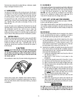
Page 10: ...rong chemicals or abrasives to clean these parts as the protective surfaces will be damaged It is important to always keep the refrigerator clean F SHUT OFF STORAGE PROCEDURE ShutofftherefrigeratorbypressingthemainpowerON OFF button to the UP OFF position Iftherefrigeratorwillnotbeinoperationforaperiodofweeks it should be emptied defrosted cleaned and the doors left ajar The ice tray should also b...

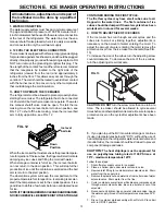
Page 11: ...nder the freezer to ON The climate control can be left on continuously or only used when temperatures require it NOTE The climate control will draw 12 volts DC power continuously when in the ON position It should be turned OFF when a charging source is not available Most LP gas appliances used in recreational ve hiclesareventedtotheoutsideofthevehicle When parkedclosetoagasolinepump itispossibleth...

Page 12: ...wer start stop the engine etc Compare the operation with the operation described in Section C Operation Instructions F FUSES The 2 way AES model is equipped with 2 fuses one for the refrigerator control system and one for the AC cartridge heater See Table below To replace fuse s proceed as follows 1 Disconnect the wall plug and the 12 volt wires 2 Remove the power module cover See FIG 6 3 Snap the...

Page 13: ...operly before starting the ice maker The refrigerator has to be connected to120voltsACbeforetheicemakercanoperate Thewater line manual shutoff valve must be open To start the ice making move the ice level bail arm to down position see FIG 12 To shut off the ice making move the ice level bail arm to fully up position see FIG 12 Whentheicemakerthermostatsensesthepresettempera tureforejectionoftheice...

Page 14: ...E 5A FUSE 3A SWITCH HEATING CA BLE R Q M LIGHT U RETAINER F OR TERMINAL BL OCK TERMINAL BL OCK S T CIRCUIT BOA RD P OWER 5 6 GREY BROWN 7 BLUE GREEN GREEN YELLOW 3 4 BLACK WHITE 2 1 Q 6 TROUBLESHOOTING Ice Maker Fails Does Not Make Ice A Check fuses or breaker supplying 120 volts AC to refrigerator and check that RV is connected to power B Check that ice level bail arm is in down position C Check ...

Reviews: