background image

5

DIAGNOSTIC SERVICE MANUAL

Dometic

®  

RM2604/2804

Refrigerators

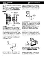
To check the high voltage cable, first disconnect DC
power at the igniter, lamp terminal block. Next, discon-
nect high voltage cable from electrode. Then reconnect
DC power to the terminal block. If sparking starts, cable
is good, DO NOT REPLACE, check the electrode (See
Sec 4.3). If no sparking, disconnect DC power at the
igniter, lamp terminal block and then disconnect high
voltage cable at the igniter. Reconnect DC power to the
terminal block. If sparking sound from igniter, replace the
high voltage cable.

4.5 DOOR SWITCH

The door switch is an open switch when the switch arm
is depressed (interior light should be off). When the
refrigerator door is open, the switch is closed (interior
light should be on). Check that the switch assembly is
properly aligned and that it is not broken. Check the
switch assembly for continuity. When the switch arm is
depressed there should not be continuity. When the
switch arm is NOT depressed there should be continuity.
If any of the checks are incorrect, replace the switch.

4.6 RELAY (3-WAY MODELS ONLY)

The relay controls the circuit to the DC heating element.
The load (amps) of the DC heating element goes
through the relay.

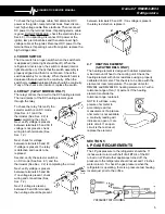
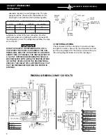
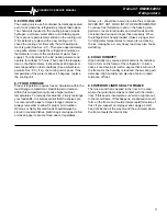
To check the relay, first verify the
selector switch is on DC mode
(See Sec. 4.1) and the
thermostat (See Sec. 2.2) is
NOT completing the circuit.
Next, verify voltage is present
between terminals 85 and 30. If
voltage is not present, check
wiring to both terminals. (See
Sec. 7.2)

Next, check for voltage
between terminals 85 and 87.
If voltage is present, the relay
is defective and needs to be
replaced.

Second, verify the selector switch is
on DC mode (See Sec. 4.1) and the
thermostat (See Sec. 2.2) is completing the circuit.

Next, verify voltage is present
between terminals 85 and 86.
If no voltage is present, check
wiring and connections (See
Sec. 7.2).

Next, if voltage is present,
between 85 and 86 terminals,
then voltage should be present

85

30

87

85

86

PRESSURE T EST HOUSING

87

between terminals 85 and 87. If no voltage is present,
the relay is defective, replace it.

4.7

HEATING ELEMENT
(3-WAY MODELS ONLY)

The heating element is designed to deliver a predeter-
mined amount of heat to the cooling unit. Check the
heating element with ohms resistance using a properly
calibrated ohm meter. This check is to be done with the
element at room temperature. The proper ohms for
RM2604 and RM2804 DC heating element is .67 with a
tolerance range of ten (10) percent. If the heating
element is outside the
tolerance range, replace it.

NOTE: It will take a very
precise ohm meter to
accurately read this
measurement. If a precise
ohm meter is not available,
a continuity reading will
indicate an open or com-
plete circuit. If an open
circuit is the test result,
replace the element.

SECTION 5

LP GAS REQUIREMENTS

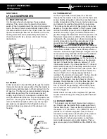
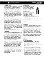
The LP gas pressure to the refrigerator should be 11
inches water column with half of all BTU’s of the RV
turned on. With all other appliances turned off, the
pressure to the refrigerator should not exceed 12 inches
water column. To check the gas pressure when the
refrigerator is operating, there is a pressure test housing
located just prior to the orifice.

85

85

Summary of Contents for RM2604

Page 1: ... accurate analyses of certain conditions Provided is a diagnostic chart leading a qualified mechanic into the service manual pages to locate and solve symptoms which may occur Dometic has continued its commitment in providing service people with this the most up to date information about servicing Dometic RV accessories Form No 3 106930 005 2 96 Replaces 05 1409 1 93 ...

Page 2: ...5 4 6 4 7 Relay _ _ _ _ _ _ _ _ 5 Heating Element _ _ _ _ ___ 5 SECTION 5 LP GAS REQUIREMENTS 5 SECTION 6 LP GAS COMPONENTS iii i z 6 9 6 10 6 11 Shut Off Valve 6 Filter 6 Thermostat 6 By pass Screw 6 Safety Valve 7 Thermocouple 7 Burner 7 Flue Baffle 7 Flue Cap 7 Flue Tube 7 Orifice 7 SECTION 7 WIRING 7 1 External Wiring _ ___ _ _ _ _ _ _ _ _ _ 7 7 2 Internal Wiring 8 SECTION 8 OTHER Leveling 9 V...

Page 3: ...ture 8 5 Cooling Unit 8 6 LP Gas 5 Thermostat 6 3 Filter 6 2 Orifice 6 11 Burner 6 7 Flue Baffle 6 8 Flue Tube 6 10 AC Volts 1 Heating Element 2 1 Thermostat 2 2 Switch 4 1 Wiring 7 2 Level 8 1 Ventilation 8 2 Ambient Temperature 8 5 Air Leaks 8 3 Thermostats 2 2 6 3 Cooling Unit 8 6 AC Volts 1 Heating Elements 2 1 Thermostat 2 2 SYMPTOM SYMPTOM SYMPTOM SYMPTOM SYMPTOM CAUSE CAUSE CAUSE CAUSE CAUS...

Page 4: ...couple 6 6 Flue Baffle 6 8 Flue Cap 6 9 Orifice 6 11 Burner 6 7 Food Storage 8 7 Air Leaks 8 3 Interior Liner Seal to Frame 8 9 High Humidity 8 8 Wiring 7 2 Door Switch 4 5 Door Position 8 4 DC Volts 3 Heating Element 4 7 Switch 4 1 Wiring 7 2 Relay 4 6 DC Volts 3 Heating Element 4 7 Relay 4 6 10 Insufficient cooling on gas Cools properly on electric 11 Freezes on electric cools properly on gas 12...

Page 5: ... models only DC voltage must be supplied to the terminal block or blocks 2 terminal blocks on 3 way models at the rear of the refrigerator The operational range is 10 5 to 15 volts DC Connecting the refrigerator to an unregulated converter can result in improper operation of the refrig erator Check for proper voltage at the terminal block or blocks at the back of the refrigerator If power is outsi...

Page 6: ... read a pulsating voltage If not replace the igniter If all of the previous checks are correct the igniter is good DO NOT REPLACE The pulsating voltage allows a lamp to illuminate on the front of the refrigerator to advise the customer spark has been produced To check the lamp first verify it is wired correctly Next verify the lamp receptacle is receiving the signal if so and lamp is not illuminat...

Page 7: ...ec 7 2 Next check for voltage between terminals 85 and 87 If voltage is present the relay is defective and needs to be replaced Second verify the selector switch is on DC mode See Sec 4 1 and the thermostat See Sec 2 2 is completing the circuit Next verify voltage is present between terminals 85 and 86 If no voltage is present check wiring and connections See Sec 7 2 Next if voltage is present bet...

Page 8: ...net temperature should be approximately 40 de grees Fahrenheit To check the calibration of the thermostat place a container of water in the cabinet of the refrigerator and operate at mid range setting until the thermostat is satisfied Then check the temperature of the water It should be approximately 40 degrees We do not recommend any calibration in the field If calibration is not correct replace ...

Page 9: ...baffle assembly flue baffle and wire for the RM2604 is 31 9 16 inches and for the RM2804 is 37 1 8 inches The flue baffle itself for the RM2604 is 3 4 inch wide and 5 1 4 inches long for the RM2804 is 3 4 inch wide and 6 inches long The proper baffle position for the RM2604 is 1 5 8 inches from the burner to the bottom of the baffle for the RM2804 is 1 3 4 inches from the burner to the bottom of t...

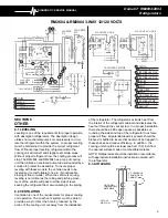
Page 10: ...WITH A RELAY MOUNTED EITHER IN THE TOW VEHICLE OR IN THE RECREATIONAL VEHICLE THIS RELAY WILL AUTOMATICALLY CUT OUT THE REFRIGERATOR WHEN THE MOTOR IS STOPPED SWITCH KEY RELAY BATTERY RV BREAKER POINT IGNITION COIL BATTERY ENGINE 12V DC HEATER REIGNTER A ND INTERIOR L IGHT 4a 2 G H 1 120 V OLTS A C E K 4 1 1 2 1 F 4 1 2 D I J 1 1 C 2 3 1 N L 120 V OLTS A C WHITE BLACK GREEN GREEN YELLOW SWITCH THE...

Page 11: ...ced by the action of the cooling unit out away from the installation of the refrigerator The refrigerator extracts heat from the interior of the refrigerator cabinet and dissipates the heat out through the vent system In a proper installation there should be as little open space as possible sur rounding the sides and top of the refrigerator to achieve proper air flow All potential dead air pockets...

Page 12: ...cause insufficient cooling as well as rapid formation of frost 8 4 DOOR POSITION The door position can be checked by observing any misalignment of the door in relation to the frame To correct an alignment of the door loosen the hinge screws slightly and re orient the door in the proper position Hold the door in its new position and carefully retighten the hinge screws If the door needs more adjust...

Page 13: ...not covered with paper or large storage containers Always remember to allow for proper air circulation Odorous or highly flavored foods should always be stored in covered dishes plastic bags or wrapped in foil or waxed paper to prevent food odors Vegetables lettuce etc should be covered to retain their crispness NEVER PUT HOT FOOD INTO THE REFRIGERATOR To reduce frost formation in and on the freez...

Reviews: