background image

24

COOLING UN IT REPLACEMENT - RM36C,  RM46,  RM47,  RM66,  RM67

Remove the refrigerator from its recess as follows:

1.

2.

3 .

4 .

5.

6.

7.

Check that refrigerator is empty and remove

ice tray.

Turn off gas bottle.

Disconnect gas line to inlet valve

CAUTION: Use a backup wrench to prevent

undue rotation.

Unplug the electric line from the trailer

o u t l e t .

Remove the 4 screws in rear front f fame.

Check for any additional screws which the

vehicle manufacturer may have used to

fasten the refrigerator in place.

Carefully slide the refrigerator straight

out of its recess.

To remove the cooling unit from the cabinet,

proceed as follows:

1.

2.

3 .

4 .

5 .

6 .

Place the refrigerator on a work bench of

suitable height.

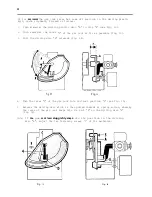
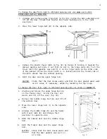
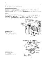
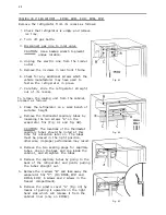
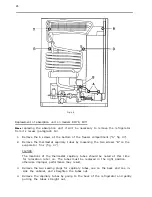
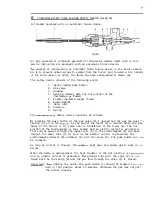
Remove the thermostat capillary tubes by

loosening the two screws “A” on the

evaporator fins (Fig. 41 and fig. 42).

CAUTION: The locations of the thermostat

capillary tubes should be noted at this

time for relocation later on. The tubes

must be placed in the right position,

 i 

Fig. 41

RM66

RM67

Fig. 42

otherwise, improper performance may result.

Remove the two sealing plugs for capillary

tubes, one on the back and one inside the

cabinet, and straighten the tubes.

Remove the capillary tubes by going to the

back of the refrigerator and gently pulling

the tubes straight out.

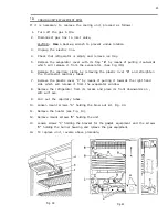
Remove the 4 screws “B” and take away the

evaporator fins “C”. (On RM46, RM47 and

RM66, RM67,  6 screws and 2 screws in the

freezer compartment).

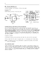
Remove the plastic cover “A” (Fig. 43) by
means of pulling it upwards on the right

hand side which will release it from the

cabinet liner (only on RM36C).

Fig. 43

Summary of Contents for RM24A

Page 1: ...441 Bonelli St City of Industry CA 91746 81 8 968 9431 Canada DOMETIC DISTRIBUTION INC 866 Langs Drive CambrIdge Ontario N3H 2N7 Canada 51 9 65 3 439 0 Edition1 Publication No 4528 E Service May 1973...

Page 2: ...ing unit 22 Cooling unit replacemen t 23 GAS ELECTRIC EQUIPMENT Gas equipment for RM24 28 Dual electri c equipment for RM24 29 Car electric equ ipment for RM36C RM46 RM47 RM66 RM67 RM76 RM77 _ _ _ _ 3...

Page 3: ...ed in place with the door pan and magnetic gasket Equipment Fool proof electric gas interlock system Thermo electric flame failure device Flint lighting system The electric and the gas thermostats are...

Page 4: ...12 volts D C 2 INSTALLATION INSTRUCTIONS For LP gas and electric operation in Motor Homes and Recreational Vehicles General instructions The refrigerators outlined herein have been design certified un...

Page 5: ...ck up wrench to prevent undue rotation of the gas cock For hook up and servicing purpose the lower vent is constructed as a lift out panel The gas supply system must incorporate a pressure regulator t...

Page 6: ...iding valuer calculated in consideration of 0 5 V voltage drop about 7 input loss in the connection cables without taking into account the losses at the terminals Maximum length of two conductor cable...

Page 7: ...already fitted on the front frame of the refriger ator r Be careful not to damage the sealing strip applied to the bottom of the enclosure when the refrigerator is put in place Any space between the...

Page 8: ...torage compartment Clearance B from rear of condenser Clearance C on top of condenser Refrigerator model 1 RM66 RM76 RM67 RM77 See minimum ventilation height figures Kit No 1 RM24 comprising Upper sid...

Page 9: ...vent Dometic V 2019 Lover side vent Dometic RM2217 see Fig 6 Dimensions pertaining to the installation are shown under measurements VENTING MEANS Fig 1 Roof vent for Kit No 3 Dometic V 2019 c Cutout s...

Page 10: ...et Refrigerator Overall dimen models A B Depth Width RM24 478 486 RM36C 556 513 RM46 RM47 631 547 RM66 RM67 631 547 RM76 RM77 625 595 ions C Height 562 720 785 985 1435 e Cabinet overall dimensions C...

Page 11: ...e refrigerator are and will year remain absolutely gas tight Check at least twice a of kinks and sharp ends The gas line should be free After installation the gas checked for leaks up to the periodica...

Page 12: ...ble fig 13 3 Pull the driving disc A outwards fig 14 3 WI Fig 13 Fig 14 4 Turn the lever C of the gas cock into vertical position D see fig 15 3 Release the driving disc which is then pulled inwards b...

Page 13: ...lation round the unit s parts behind the cabinet is unrestricted Good refrigeration performance is dependent upon adequate ventilation of the refrigeration unit 3 UNUSED OR ABANDONED REFRIGERATORS An...

Page 14: ...l gently so that the free side of the panel can be slipped into corresponding groove of the door frame 5 Push the panel downwards so that the lower horizontal edge of the panel is fitted in the bottom...

Page 15: ...d in a set consisting of the gasket and of necessary fastening strips and screws and is ordered under part No 290 07 33 00 3 The replacement is made as follows 1 Remove the door and place it with its...

Page 16: ...revent scratches and dents 4 The screws holding the door pan in place are hidden by the door gasket Pull the door gasket to one side and remove all screws A see fig 24 from the door plate 6 REPLACEMEN...

Page 17: ...the carrier A inwards by means of a blunt mandrel or pin fig 27 and remove the shutter Pry the spring housings B fig 27 away from the lining so that it snaps out and turn the spring housings downwards...

Page 18: ...e screwdriver is applied in front of one of the plastic tongues B fig 29 which hold the inner panel and the shutter front together 5 Replace the sealing gasket round the inner panel and snap the inner...

Page 19: ...latch should face the cabinet opening 4 Refit the door and the upper hinge bolt CAUTION Check that the door closes easily and that the door gasket seals well on all sides If necessary adjust by reset...

Page 20: ...ervicing an absorption system refrigerator piping do not puncture or break the Should a break occur and ammonia contact the skin wash the affected area immediately with clear vater vessel Do not attem...

Page 21: ...ng device WATER SEPERATOR Fig 36 Cooling Unit 351A gas electric operation for model RM67 with defrosting device Cooling Unit 352A gas electric operation for model RM66 without defrosting device Coolin...

Page 22: ...uid balance to the unit The temperatures on various parts of a unit vary continuously when it is operating on thermostatic control and it is impossible to base a judgment on the symptoms given unless...

Page 23: ...lease the capillary clamp by removing the plastic rivet B and straighten the thermostat capillary tubes Remove the plastic cover C by means of pulling it towards the right hand side which will release...

Page 24: ...e height Remove the thermostat capillary tubes by loosening the two screws A on the evaporator fins Fig 41 and fig 42 CAUTION The locations of the thermostat capillary tubes should be noted at this ti...

Page 25: ...evaporator flange otherwise improper cabinet performance may result Remove the connection block cover on the side of the boiler case and disconnect the two electrical wires where they join the heater...

Page 26: ...y loosening the two screws B on the evaporator fins fig 47 CAUTION The locations of the thermostat capillary tubes should be noted at this time for relocation later on The tubes must be replaced in th...

Page 27: ...w on the burner housing and remove the burner housing from the boiler case Carefully slide absorption unit straight out of the cabinet CAUTION Be careful not to damage the inner liner and the location...

Page 28: ...with nipple nut 11 Thermostat Ranco V35 12 By pass screw 13 Thermos tat knob 14 Screw 15 Indicator 16 Thermo coup le 17 Lock nut 18 Washer 19 Distance tube 20 Distance nut 21 22 23 24 25 26 27 28 29 3...

Page 29: ...ock with bracket 28 Screw 29 Protection tube 30 Thermostat Ranco A50 31 Nut 32 Thermostat cover 33 Screw 34 Plastic rivet 35 Capillary clamp 36 Grommet 37 Screw 38 Clip 39 Switch knob with dial 12 DUA...

Page 30: ...ary tube for gas thermostat 15 Shut off valve 16 Push button for lighter 17 Piezo lighter 18 Lighter electrode 19 Knob for releasing safety device 20 Knob for gas thermostat 21 Fuel selector LP gas l1...

Page 31: ...31 3 27 _ il ___ ____ 2 i Fig 51...

Page 32: ...ss flame it will be necessary to clean the thermostat valve and valve seat Note The thermostat will not close to by gass on setting O at least S C 40 F unless the thermostat bulb is cooled down to Pro...

Page 33: ...let placed l 3 into flame 15 THE GAS BURNER see fig 55 The burner has the jet horizontally located and the burner mixing tube is formed as a bend with vertical outlet The pri mary air inlets are pre s...

Page 34: ...Xodel BM24 RM36C BM46 RM47 BM66 BM67 R 76 RM77 Baffle Width x Length nun inches 10 x 100 3 a x 4 20 x 100 3 4 x 4 20 x 100 314 x 4 20 x 100 3J4 x 4 20 x 150 314 x 6 75 3 75 3 75 3 75 3 75 3 Part Jo B...

Page 35: ...button 1 the gas valve 2 is opened and the gas can pass c e housing 3 on to the burr r At the burner the feeler 4 is located When the gas flame of the burner is lit some heat is transferred to the fee...

Page 36: ...the feeler is located as in figure 7 Check that no burrs are inside valve housing B which nay cause leaks Screw plug A onto the valve housing B taking care not to damage the threaded hole in the alum...

Page 37: ...from the cord and iemove the heater Make sure the new heater is fully inserted before bending back the wire clip with caution or it might snap off Reset the electric connections Be careful to put the...

Page 38: ...k I I I I Brown I Rrd P 4 I 110 Volts I Heating element Terminal block Switch Fig 64 1lOV for RM36C RM46 RM47 RM66 RM67 RM76 RM77 Heater Thermostat Fig 6 5 l2V llOV for RM36C RM46 RM47 RM66 RM67 Term...

Page 39: ...ows If the gauge is filled with water to zero and the lower column is 5 5 inches 140 mm below zero the other column will also be 5 5 inches 140 IX By adding the tvo together 5 5 5 5 11 inches 280 mm w...

Page 40: ...nnot be inadvertently used at the same time 23 GAS OPERATION See Fig 70 and 71 1 Ensure that the voltage change switch A is at the OFF position 2 Turn the gas valve C so that the handle is in line wit...

Page 41: ...of the flame failure safety device and after 5 10 seconds press the button E to the piezo lighter The pressing may have to be repeated Through the reflector F it can be observed that the burner is li...

Page 42: ...of the vehicle so that the bubble is in the center ring of the level Fig 7 7 When the vehicle is on tow the continuous rolling and pitching movement vi11 not affect the refrigerator as long as the mov...

Page 43: ...the lining with lukewarm water to which a little baking soda may be added Dry thoroughly especially around door frames and door gasket Warm water only should be used to wash the cooling evaporator ice...

Page 44: ...Xake sure that all gas appliances are closed Test gas connections and all joints in the gas line with soap and water solution up to and including gas cock Never look for a leak with an open flame Use...

Page 45: ...against the serrated wheel Replacement of the serrated vheel RM24 If after several years of use the lighter does not function properly even with a new flint the serrated vheel might be worn out and n...

Page 46: ...stening the electrode on the burner housing make sure that the insulation plate is properly fitted between the burner housing and the electrode see fig 78 Replacement of Piezo lighter complete 1 Relea...

Page 47: ...of appropriate voltage type see table page 37 8 Intermittent electricity supply Look for loose connections or other reason for interruption and correct h Drop in supply voltage The supply voltage sho...

Page 48: ...rt in valve of the thermostat Remedy Remove any restriction See par 28 Fit new bottle Adjust position of feeler point in flame See par 15 Clean by pass screw with alcohol and by blowing through with a...

Page 49: ...tion in voltage supply No loose electric connections Thermostat intact 16 No unit leaks 17 Safety valve intact 45 PACKING OF DEFECTIVE UNITS Particular attention must be paid to the packing of a repla...

Page 50: ...ion CJ that several causes can be responsible for 22 2 s 2 the one effect The real cause or causes u r 8 u G 4 o should bc determined by a process of elipi u 24 2 J b See paragraph No nation investiga...

Page 51: ...ce clogged The thermocouple tip not in position No contact between thenwcouple and safety valve mamet Faulty safety valve magnet Improper maxisum flame By pass flame too small I 48 Gauze in burner hea...

Page 52: ...same time check the flue baffle that it is clean and free from soot Heavy soot formation indicates improper functioning of the burner Clean baffle and flue Further clean cooling unit and floor under r...

Reviews: