


7
GAS, AC AND DC OPERATION
UNIVERSAL LP GAS OPERATION
Before starting the refrigerator, open the shutoff valve of the
gas bottle (check that there is enough gas). Open any on-
board shutoff valve.
Start the refrigerator by turning turn knob
1.
A
to
position (GAS).
Turn the thermostat knob
2.
B
to position 4.
Press and hold button
3.
C
and push button
D
for the
piezo igniter several times to light the burner.
This can be observed on the flame indicator
E
.
When the flame is lit, the red indicator is in the
green field. (ON).
After the gas is lit keep button
4.
C
pressed for 10 s.
Release the button and check that the red indicator
is in the green field, (ON).
Note!
After changing a ULPG bottle, or after a long shut off pe-
riod, the gas line is likely to be filled with air. You may have
to repeat the lighting procedure several times to purge the air
out of the gas lines.
230-240 V AC OPERATION
Before operating the refrigerator, check that the voltage
stated on the data plate is the same as the main voltage in use.
Check to be sure that the power cord is properly
1.
connected to the power supply.
Turn the knob
2.
A
to the position marked “AC” for
230-240 volt AC operation.
Turn the thermostat knob
3.
B
to position 4.
GENERAL ADVICE AND INFORMATION
Make sure defrosting is carried out periodically
•
The refrigerator should be kept clean and dry with the
•
door left open when it is not to be used for some time.
Ensure that liquids or items with a strong odour are well
•
packaged.
Service and maintenance must be done on a regular sched-
•
ule to keep the refrigerator operating properly, efficiently
and safely. The service should be performed by qualified
personnel only.
Avoid spraying water through the refrigerator vents while
•
washing your RV.
Sodium chromate is used for corrosion protection (less than
2 weight % of the coolant).
WARNING
The sealed cooling system must not be opened.
It contains corroding chemicals under high pressure.
6
!
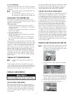
OPERATING INSTRUCTIONS
ON/OFF, Fuel selector switch
A.
Thermostat knob, Gas/Electric
B.
Flame failure safety valve push-button
C.
Piezo igniter
D.
Flame indicator
E.
ABSORPTION REFRIGERATOR SYSTEM
In an absorption refrigerator system, ammonia is liquefied in
the finned condenser coil at the top rear of the refrigerator.
The liquid ammonia then flows into the evaporator (inside the
freezer section) and is exposed to a circulating flow of hydro-
gen gas, which causes the ammonia to evaporate, creating a
cold condition in the freezer.
The tubing in the evaporator section is specifically sloped to
provide a continuous movement of liquid ammonia, flowing
downward by gravity through this section.
If the refrigerator is operated when it is not level and the ve-
hicle is not moving, liquid ammonia will accumulate in sec-
tions of the evaporator tubing. This will slow the circulation
of hydrogen and ammonia gas, or in severe cases, completely
block it, resulting in a loss of cooling.
Note!
Any time the vehicle is parked for several hours with
the refrigerator operating, the vehicle must be levelled to
prevent this loss of cooling.
When the vehicle is moving, the levelling is not critical, as
the rolling and pitching movement of the vehicle will pass
to either side of level, keeping the liquid ammonia from ac-
cumulating in the evaporator tubing.
CONTROL PANEL
A
E
D
C
B
WARNING
Whilst mobile:
- Do not operate the refrigerator on gas.
- Turn off the gas bottle
.
6
!
ULP
Summary of Contents for RM2350
Page 12: ...54 219 MAW41A01...