4
INSTALLATION
GENERAL INSTRUCTION
This appliance is designed for storage of foods and
storage of frozen foods and making ice.
This appliance is certified under the latest edition of
ANSI Z21.19•CSA 1.4 Refrigerators using gas fuel.
The installation must conform with local codes, or in ab-
sence of local codes, the following standards as appli-
cable.
In the U.S. the installation must conform with:
1. Recreational Vehicles Code, ANSI A119.2 (latest
edition)
2. Manufactured Home Construction and Safety
Standard, Title 24 CFR, Part 3280.
If an external electrical source is utilized, the refrigera-
tor, when installed, must be electrically grounded in ac-
cordance with local codes or, in the absence of local
codes, the National Electrical Code, ANSI/NFPA 70 - (lat-
est edition).
In CANADA, the installation must conform with:
1. CSA Z240 RV Series, Recreational Vehicles.
2. Current CSA Z240.4, Gas-equipped Recreational
Vehicles and Mobile Housing.
If an external electrical source is utilized, the refrigera-
tor, when installed, must be electrically grounded in ac-
cordance with local codes or, in the absence of local
codes, the Canadian Electrical Code, CSA C22.1, Parts
I
and
II
- (latest edition).
VENTILATION
The installation shall be made in such a manner as to
provide necessary air circulation over thr cooling unit.
Openings for air supply shall have a minimum dimen-
sion of not less than 1/4 inch.
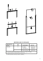
Proper installation requires one lower fresh air intake and
one upper exhaust vent. The ventilation kits shown in
this instruction manual have been certified for use with
the refrigerator models listed in the table. For “Certified
Vent System Kits” see page 13.
The ventilation kits must be installed and used without
modification. The lower vent of the recommended kits is
provided with proper size openings.
The flow of ventilating air must not be obstructed.
The lower side vent is fitted with a panel, which provides
an adequate access opening for ready serviceability of
the refrigerator. This should be centered on the back of
the refrigerator.
ELECTRICAL CONNECTION
120 Volts AC Connection
The refrigerator is equipped with a three-prong (ground-
ing) plug for your protection against shock hazards and
should be plugged directly into a properly grounded three-
prong receptacle. DO NOT cut or remove the grounding
prong from this plug. The free length of the cord is 2 feet
and therefore recommended that the receptacle be lo-
cated to the right side of the refrigerator (viewed from
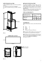
the rear). The receptacle should be 3” (from the bottom
of the plastic receptacle) above the refrigerator mount-
ing floor. (see FIG. 3). This allows easy access through
the vent door. The cord should be routed to avoid direct
contact with the burner cover, flue cover or any other
components that could damage the cord insulation.
12 Volts DC Connection
The refrigerator model NDE1292 require a continuous
12 volt DC supply to operate the control system.
The connection is made to the positive (+) and negative (-)
terminals of the terminal block on the back of the refrig-
erator. (See FIG. 1). Correct polarity must be observed
when connecting to the DC supply.
Do not use the chassis or vehicle frame as one of the
conductors.
Connect two wires at the refrigerator and route to the
DC supply.
The distance the current must travel from the battery to
the refrigerator dictates the AWG wire size to be used.
Should the wire be too small for the distance, a voltage
drop will result.
Recommended wire sizes are shown below.
The wires from the battery to the refrigerator must be of
large enough size to handle the load. The connections
must be clean, tight and free from corrosion.
MAXIMUM TOTAL CONDUCTOR WIRE LENGHT
(in feet and meters)
Wire lenght
AWG
17 ft.
14
5 m
27 ft.
12
8 m
FIG. 3
120 Volt AC
receptacle
3’’

