Dometic 4410N, Operation Manual
The Dometic 4410N, a top-of-the-line appliance, comes with a comprehensive Operation Manual. This manual is available for free download on our website, providing users with essential instructions and guidance. Get your hands on the manual today at manualshive.com and maximize the full potential of your Dometic 4410N.
Share
Download


Reviews:
No comments
Related manuals for 4410N

Jabsco 37010 Series
Brand: Xylem Pages: 4

Laveo DF1045
Brand: Dry Flush Pages: 15

K-5401X
Brand: Kohler Pages: 48

VEIL K-5401T
Brand: Kohler Pages: 61

Novita K-BN330-N0
Brand: Kohler Pages: 32

ME by Starck 280931 93 Series
Brand: DURAVIT Pages: 8
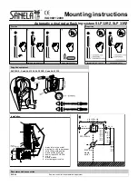
SLP 32RZ
Brand: Sanela Pages: 2

PARMA E157
Brand: FV Pages: 2

ATS-800
Brand: Lotus Pages: 12

Soft LED 805-02
Brand: DUSCHY Pages: 2


