


3 BC
2201SS User Manual
www.dolphinsolutions.co.uk
General safety information:
-- N
OTE: Do not install dryer over washbasin
--
Disconnect power at the
service breaker before installing or servicing.
NOT FOR HOUSEHOLD USE - MAY CAUSE BURNS.
" IMPROPRE A L'USAGE DOMESTIQUE - PUET OCCASIONNER."
This product is intended
for installation by a qualified service person.
Use 1.5 mm² solid conductor for wiring.
All units must be supplied
with a 3-wire service. The ground wire must
be connected to the dryer's backplate.
Failure to properly ground
unit could result in severe electrical shock
and/or death.
Installation
Type Y attachment
If the power supply cord is damaged, it must be replaced by the manufacturer
or its service agent or a similar qualified person in order to avoid a hazard.
Means for disconnection must be incorporated in the fixed wiring in
accordance with the wiring rules.
1. Make sure power supply breaker is switched off. Installation must be carried out in accordance
with the current edition of the local wiring regulations code having jurisdiction. Installation should
be performed only by a qualified electrician.
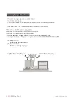
2. Place template against wall at desired height (see mounting height recommendations) and mark
locations of 4 mounting holes and wire service entry at knockout (KO) location.
Note:
For two or more dryers, dryers should be no closer than 24 inches (610 mm) on center.
3. Remove and retain 2 cover screws and cover.
4. Connect supply wires to terminal block where indicated and connect ground wire to base plate
with ground screw
A. Connect the live wire (colored red or black or brown ) to the terminal block marked "L".
B. Connect the neutral wire (colored white or blue) to the terminal block marked "N".
C. Connect the ground wire (colored green or green and yellow) to the green screw marked " ").
Note
that colors of live and neutral wires depend on voltage of supply service.
5. Replace cover. Do not over-tighten screws.
Connections:


