8
07.10.15 en / 477
Technical Data
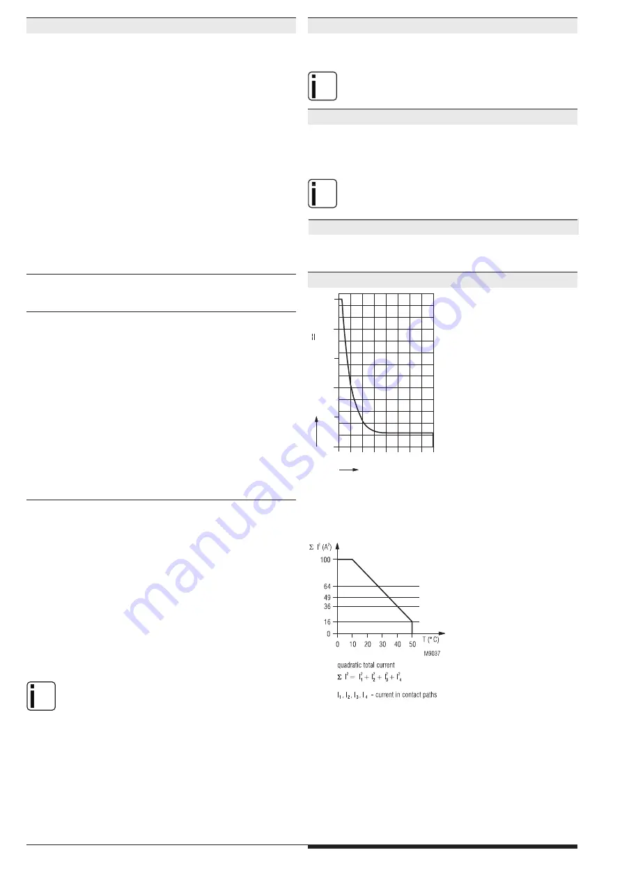
Characteristics
Limit curve for arc-free operation
Switching current I
Switching
voltag
e
U
[
V]
safe breaking, no continuous arcing
under the curve, max. 1 switching cycle/s
[A]
0
50
100
200
250
150
1
2
3
4
5
6
7
8
M7073_
a
Quadratic total current limit curve
Vibration resistance:
Amplitude 0.35 mm
Frequency 10 ... 55 Hz, IEC/EN 60 068-2-6
Shock resistance:
Acceleration:
10 g
Pulse duration:
16 ms
Number of shocks:
1000 per axis on three axes
Climate resistance:
0 / 050 / 04
IEC/EN 60 068-1
Terminal designation:
EN 50 005
Wire connection:
1 x 2.5 mm
2
stranded wire with sleeve, or
1 x 4 mm
2
massive, or
2 x 1.5 mm
2
stranded wire with sleeve
DIN 46 228-1/-2/-3/-4
Wire fixing:
Plus-minus terminal screws M3,5
box terminals with wire protection
Surge supression:
When connecting inductive loads to the
relay outputs (contactor coils, valves,
electric brakes) surge supressor elements
like diods, capacitros, RC combinations,
etc. have to be connected directly to the
connection terminals of the controlled
devices, keeping the connection wires
as short as possible.
Mounting:
DIN rail
IEC/EN 60 715
Dimensions
Width x height x depth:
45 x 84 x 121 mm
Safety Related Data for E-STOP
Values according to EN ISO 13849-1:
Category: 4
PL: e
MTTF
d
:
193.3 a
DC
avg
:
98.3
%
d
op
:
365
d/a (days/year)
h
op
:
24
h/d (hours/day)
t
Zyklus
:
3600 s/Zyklus
=
1
/h (hour)
Values according to IEC EN 62061 / IEC EN 61508:
SIL CL:
3
IEC EN 62061
SIL
3
IEC EN
61508
HFT
*)
: 1
DC
avg
:
98.3
%
SFF
99.6 %
PFH
D
:
4.06E-10 h
-1
Safety Related Data for light curtains ,safety gates or two-hand
Values according to EN ISO 13849-1:
Categorie: 4
PL: e
MTTF
d
:
30.4 a
DC
avg
:
99.0
%
d
op
:
220
d/a (days/year)
h
op
:
12
h/d (hours/day)
t
Zyklus
:
138 s/Zyklus
Values according to IEC/EN 62061 / IEC/EN 61508:
SIL CL:
3
IEC/EN 62061
SIL
3
IEC/EN 61508
HFT
*)
: 1
DC
avg
:
99.0
%
SFF
99.6 %
PFH
D
:
7.91E-09 h
-1
*
)
HFT = Hardware-Failure Tolerance
nfo
The values stated above are valid for the standard type.
Safety data for other variants are available on request.
The safety relevant data of the complete system has to be
determined by the manufacturer of the system.
Ordering Example
BH 5911.03/00MF0 DC24V
3 NO contacts
BH 5911.22/00MF0 DC24V
2 NO contacts, 1 NC contact
CSA-Data
Wire connection:
60°C / 75°C copper conductors only
AWG 20 - 12 Sol Torque 0.8 Nm
AWG 20 - 14 Str Torque 0.8 Nm
nfo
Technical data that is not stated in the CSA-Data, can be found
in the technical data section.
CCC-Data
Thermal current I
th
:
4 A
Switching capacity
to AC 15:
3 A / AC 230 V
IEC/EN 60 947-5-1
to DC 13:
1 A / DC 24 V
IEC/EN 60 947-5-1
nfo
Technical data that is not stated in the CCC-Data, can be found
in the technical data section.
E. DOLD & SÖHNE KG • D-78114 Furtwangen
e-mail: [email protected] • internet: http://www.dold.com
•
PO Box 1251 • Telephone (+49) 77 23 / 654-0 • Telefax (+49) 77 23 / 654-356


