2
11.01.21 en / 335A
- If standstill is not detected, the braking cycle is interrupted after 20 s.
- The brake current switches off after 0.5 sec standstill detection.
- After activation of the start input mains frequency, phase sequence and
presence of all 3 phases is checked.
- Internal temperature monitoring protects the thyristors. By switching on
or off of the power supply this fault can be reset after the temperature
has dropped.
- To protect the power circuit the current is monitored in L1-T1. If the fixed
settings are exceeded, the device switches off and a failure indication is
displayed by a red LED.
- Monitoring of phases and phase shift protects the motor or the
system. After removing the fault this error can be reset by switching
the power supply on and off.
-
External bimetallic switches or PTC-thermo sensors are used to
monitor motors on thermal overload. (variant /_1_). Overload results in
disconnection of the motor and failure indication via the red error LED.
After a cooling down period for the motor, the failure can be reset reset
switching the power supply OFF and ON again.
Variation of speed is not possible with this device. Without load a softstart
cannot be achieved. It is recommended that the softstart is protected by
superfast semiconductor fuses rated as per the current rating of the softstart
or motor. However, standard line and motor protection is acceptable, but
for high starting frequencies motor winding temperature monitoring is
recommended. The softstarter must not be operated with capacitive load
e.g. power factor compensation on the output.
In respect to safety of persons and plant only qualified staff is allowed to
work on this device.
Green LED: perm. on:
- When auxiliary supply connected or
bypass relay energized
flasher light: - While starting and breaking
Monitoring relay 1
Yellow LED: perm. on:
- When contact 13-14 switched on
Monitoring relay 2
Yellow LED: perm. on:
- When contact 13-24 switched on
Monitoring relay 4
Yellow LED: perm. on:
- When contact 43-44 switched on
Red LED:
steady
flashing:
- Motor current is > 3 x device current
Red LED:
flasher light : - Error
1*
)
:
- Overtemperature on thyristor (internal)
2*
)
:
- Overtemperature on motor or broken wire in
sensor circuit P
1
/ P
2
or bi-metal contact
at sensor circuit P
2
/ P
3
has tripped (ooen)
3*
)
:
- Short circuit on sensor circuit P
1
/ P
2
4*
)
:
- Phase failure
5*
)
:
- Incorrect phase sequence,
exchange connections on L1 and L2
6*
)
:
- Incorrect frequency
7*
)
:
- Incorrect brake circuit
9*
)
:
- Incorrect internal temperature sensor
10*
)
:
- Incorrect RAM
13*
)
:
- Overcurrent
14*
)
:
- Brake current to high
15*
)
:
- Overcurrent at end of ramp up
16*
)
:
- Internal communication error
17*
)
:
- Overcurrent on bridging relay
1-17*
)
= Number of flashing pulses in short sequence
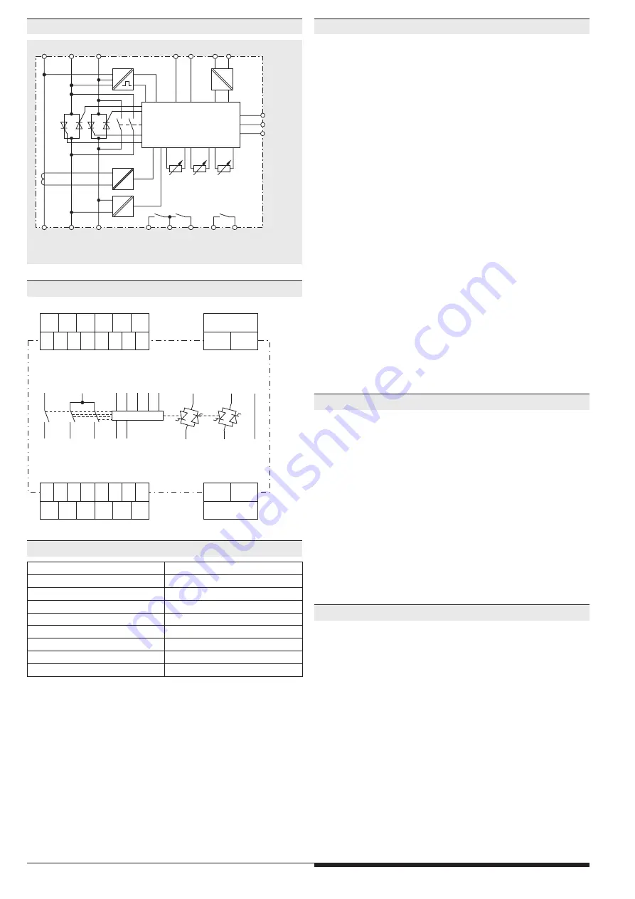
Monitoring Features
Notes
Indicators
Block Diagram
Circuit Diagram
Terminal designation
Signal description
X1, X2
Start-/Stop-Signal
13, 14
Monitoring relay 1 bridging operation
13, 24
Monitoring relay 2 Ready
43, 44
Monitoring relay4 Standstill
A1(+) , A2
Auxiliary voltage DC 24 V
L1, L2, L3
Phase voltage
T1, T2, T3
Motor connection
P1, P2 , P3
PTC thermal sensor, bi-metal contact
Terminal Connection
M10200_b
13
A1+
X1+
24
A2
X2
L1
T1
L3
T3
14
P3
P2
P1
43
44
L2
T2
L2
43
44
A2
T2
L3
L1
T3
T1
A1 X1 P1 P2 P3
X2
13
24
14
Variante /_1_
L1
L2
L3
T1
T2
T3
M10206_b
M on
t on
I Br
14
43
13
44
24
I
U
U
U
U
P1
variant
/_1_
P2
P3
micro control
A1+ A2
X1+ X2


