background image

10

999287902 - 02/2020 

Original Operating Instructions 

Hand pump CFT 700bar, Hand pump CFT U

© SPX FLOW INC.

Form No. 102842 

Rev. 16  June 20, 2016

8

1. Two-way Valve

Pumps with a two-way valve are for use with singleacting cylinders.

A.  1. To extend the cylinder, turn the valve knob counterclockwise to a closed (seated) position. 

Note: 

+DQGWLJKWRQO\

 Work the pump handle up and down to build pressure.

B.  2. To release pressure, open the valve slowly by turning the knob clockwise to control the load.

2. Four-way Valve

Pumps with a three-position, four-way valve are for use with double-acting cylinders. The hose  
connection for extending a cylinder can be made to either port. With the handle in the forward position, the 

ÀXLGLVGLUHFWHGWRWKHWRSÀXLGSRUW7RPDLQWDLQKROGSUHVVXUHVWRSWKHSXPSLQJDFWLRQ:KHQWKHYDOYH
KDQGOHLVLQWKHFHQWHUSRVLWLRQÀXLGÀRZLVEORFNHGWRERWKSRUWV

WARNING

The operator should always release the pressure slowly.

PREVENTIVE MAINTENANCE

IMPORTANT

$Q\UHSDLURUVHUYLFLQJWKDWUHTXLUHVGLVPDQWOLQJWKHSXPSPXVWEHSHUIRUPHGLQDGLUWIUHH


HQYLURQPHQWE\DTXDOL¿HGWHFKQLFLDQ

/XEULFDWLRQ

 Apply lubricant regularly to all pivot and rubbing points.

        Use a good grade of No. 10 motor oil or grease. Do not use dry lubricants.

1. 

%OHHGLQJ$LU)URPWKH6\VWHP

Air can accumulate in the hydraulic system during the initial set-up or after prolonged use, causing the  
cylinder to respond slowly or in an unstable manner. To remove the air:

A.  Position the cylinder at a lower level than the pump, and turn the cylinder rod end down.

B.  Extend and retract the cylinder several times without putting a load on the system. Air will be released 

LQWRWKHSXPSUHVHUYRLU)ROORZWKHÀXLGOHYHOLQVWUXFWLRQVIRU\RXUUHVHUYRLUW\SHWRUHOHDVHWKHDLUIURP
WKHUHVHUYRLUDQGWRSRIIWKHÀXLGVXSSO\

2. 

%OHHGLQJ$LU)URP7KH3XPS

:KHQWKHSXPSLV¿UVWSXWLQWRXVHRUDIWHUUH¿OOLQJWKHSXPS¶VUHVHUYRLULWPD\EHQHFHVVDU\WREOHHGDQ\

trapped air from the pump. If this is not done the pump will not function properly (will not build pressure or 
has very spongy operation).

To bleed air from the pump, turn the pressure control knob counterclockwise (CCW) (turn lever down or 
clockwise on P460 models) and operate the pump handle up and down approximately twenty times. Turn 
the pressure control knob clockwise (CW) to its full stop position (turn lever up or CCW on P460 models). 
The pump should now be bled of air and ready to use. 

Summary of Contents for 584607500

Page 1: ...300 Amstetten 999287902 02 2020 en GB The Formwork Experts Hand pump CFT 700bar Hand pump CFT U Art n 584695000 584607500 Original Operating Instructions Please retain for future reference by Doka GmbH A 3300 Amstetten ...

Page 2: ...inder CFT 20t 700bar Data on rating plate Designation Hand pump CFT 700bar Art n 584695000 Weight including oil filling in kg 12 kg 26 5 lbs Oil grade Shell Tellus S4 VX 32 Operating temperature 5 C to 55 C Hand pump CFT U Oil grade Shell Tellus S2 V46 Note Hand pump CFT U is for operation of the following hydraulic cylinders Hollow plunger cylinder CFT 60t U Hollow plunger cylinder CFT 20t U A Ha...

Page 3: ...326 Order Entry 800 541 1418 Fax 800 288 7031 powerteam com SINGLE STAGE AND TWO STAGE HYDRAULIC HAND PUMP Max Pressure See Pump Data Plate Operating Instructions for 62072 See P159 201338 TID See P12 P157 SERIES 62087 See P55 P12 SERIES P175D SERIES 64122 See P55 P19 SERIES P159 SERIES 64215 See P59 P23 SERIES P159D SERIES 64372 See P55 P30F SERIES P300 SERIES 66463 See P59 P55 SERIES P300D SERIE...

Page 4: ...H QLWLRQ SAFETY PRECAUTIONS 4 SET UP 7 GUDXOLF RQQHFWLRQV OPERATION 7 1 Two way Valve 8 2 Four way Valve 8 PREVENTIVE MAINTENANCE 8 OHHGLQJ LU URP WKH 6 VWHP OHHGLQJ LU URP 7KH 3XPS 3 Hydraulic Fluid Level 9 UDLQLQJ QG OXVKLQJ 7KH 5HVHUYRLU RU PRGHOV ZLWK 5HVHUYRLU 7 SH RU PRGHOV ZLWK 5HVHUYRLU 7 SH TROUBLESHOOTING GUIDE 11 POWER TEAM FACILITIES 13 DECLARATION OF INCORPORATION 14 ...

Page 5: ...V UHVSRQVLELOLW WR UHDG DQG XQGHUVWDQG WKH IROORZLQJ VDIHW VWDWHPHQWV 2QO TXDOL HG RSHUDWRUV VKRXOG LQVWDOO RSHUDWH DGMXVW PDLQWDLQ FOHDQ UHSDLU RU WUDQVSRUW WKLV PDFKLQHU 7KHVH FRPSRQHQWV DUH GHVLJQHG IRU JHQHUDO XVH LQ QRUPDO HQYLURQPHQWV 7KHVH FRPSRQHQWV DUH QRW VSHFL FDOO GHVLJQHG IRU OLIWLQJ DQG PRYLQJ SHRSOH DJUL IRRG PDFKLQHU FHUWDLQ W SHV RI PRELOH PDFKLQHU RU VSHFLDO ZRUN HQYLURQPHQWV VXF...

Page 6: ...XU R QRW XVH WKH KRVH WR PRYH DWWDFKHG HTXLSPHQW 6WUHVV PD GDPDJH WKH KRVH DQG FDXVH SHUVRQDO LQMXU RVH PDWHULDO DQG FRXSOHU VHDOV PXVW EH FRPSDWLEOH ZLWK WKH K GUDXOLF ÀXLG XVHG RVHV DOVR PXVW QRW FRPH LQ FRQWDFW ZLWK FRUURVLYH PDWHULDOV VXFK DV FUHRVRWH LPSUHJQDWHG REMHFWV DQG VRPH SDLQWV RQVXOW WKH PDQXIDFWXUHU EHIRUH SDLQWLQJ D KRVH 1HYHU SDLQW WKH FRXSOHUV RVH GHWHULRUDWLRQ GXH WR FRUURVLYH P...

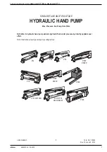
Page 7: ...une 20 2016 5 SINGLE STAGE AND TWO STAGE HYDRAULIC HAND PUMP Max Pressure See Pump Data Plate H QLWLRQ K GUDXOLF KDQG SXPS GHOLYHUV K GUDXOLF ÀXLG XQGHU SUHVVXUH E GLUHFWO DSSOLHG DQXDO effort 1RWH OOXVWUDWLRQV GHSLFW JHQHUDO SXPS FRQ JXUDWLRQV P12 P157D P159D P19 P23 P30F P30FP P157 P159 64662 64663 P300 P55 P59F P59FP P460 ...

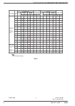
Page 8: ... 0 662 0 160 10 8 2 6 325 10000 22 700 145 65 8 B 55 901 45 738 17 2 7 8 P59F 1 2 0 550 0 130 9 0 2 1 325 10000 22 700 120 54 5 B 55 901 45 738 14 0 6 4 P59FP 1 pop off 0 550 0 130 9 0 2 1 325 10000 22 700 145 65 8 B 55 901 45 738 14 0 6 4 P157 1 2 0 650 0 160 10 7 2 6 1400 10000 97 700 140 63 5 B 152 2491 137 2245 26 0 11 8 P159 1 2 2 600 0 160 42 6 2 6 325 10000 22 700 140 63 5 B 152 2491 137 22...

Page 9: ...HPEO Couple hose to cylinder B The use of a hydraulic pressure or tonnage gauge not included is strongly recommended Remove the pipe plug from the gauge port of the valve thread the gauge into this port and seal as noted above WARNING 7R KHOS SUHYHQW SHUVRQDO LQMXU 7KH JDXJH PXVW KDYH WKH VDPH SUHVVXUH UDWLQJ DV WKH SXPS DQG F OLQGHU 3HUVRQDO LQMXU FDQ UHVXOW LI WKH ZURQJ JDXJH LV XVHG 5HOHDVH K G...

Page 10: ...ULFDWLRQ Apply lubricant regularly to all pivot and rubbing points Use a good grade of No 10 motor oil or grease Do not use dry lubricants 1 OHHGLQJ LU URP WKH 6 VWHP Air can accumulate in the hydraulic system during the initial set up or after prolonged use causing the cylinder to respond slowly or in an unstable manner To remove the air A Position the cylinder at a lower level than the pump and ...

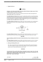
Page 11: ...WKH OOHU KROH ZKHQ WKH SXPS LV OHYHO DQG UHVWLQJ KRUL RQWDOO RQ LWV EDVH DQG WKH F OLQGHUV DUH UHWUDFWHG see Figure 2 END VIEW OIL LEVEL Figure 2 RU PRGHOV ZLWK 5HVHUYRLU 7 SH 5HPRYH WKH OOHU FDS 7KH ÀXLG OHYHO VKRXOG EH LQFK PP IURP WKH OOHU KROH ZKHQ WKH SXPS LV OHYHO DQG UHVWLQJ KRUL RQWDOO RQ LWV EDVH DQG WKH F OLQGHUV DUH UHWUDFWHG IMPORTANT 7KH SXPS VLJKW JDXJH LQGLFDWHV WKH SUHVHQFH RI K GU...

Page 12: ...KH OOHU FDS UDLQ WKH K GUDXOLF ÀXLG WKURXJK OOHU KROH B Remove the nut from the tie rod Separate the reservoir from the pump body Clean the reservoir and OWHU IMPORTANT 5HPRYLQJ WKH OWHU IURP WKH SXPS DVVHPEO FRXOG UHVXOW LQ LWV EUHDNDJH WWHPSW WR FOHDQ LW DV ZHOO DV SRVVLEOH ZLWK LW LQVWDOOHG 5HDVVHPEOH DQG OO WKH UHVHUYRLU ZLWK 3RZHU 7HDP K GUDXOLF ÀXLG 5HSODFH WKH OOHU FDS 2 RU PRGHOV ZLWK 5HVH...

Page 13: ... leaking past outlet check seat s 1 Check for dirt Reseat pump body and or replace poppet s or ball s 3XPS QRW GHOLYHULQJ ÀXLG RZ ÀXLG OHYHO LQ UHVHUYRLU KHFN ÀXLG OHYHO SHU instructions QWDNH OWHU LV GLUW 2 Remove reservoir and clean 3 Seats worn and not seating properly 3 Repair seats or replace pump body 3XPS GRHV QRW UHDFK IXOO SUHV sure RZ ÀXLG OHYHO LQ UHVHUYRLU KHFN ÀXLG OHYHO SHU instructi...

Page 14: ...apped in system 1 Position cylinder lower than pump Extend and return cylinder several times Follow bleeding instructions 7RR PXFK ÀXLG LQ UHVHUYRLU KHFN ÀXLG OHYHO SHU instructions 3XPS KDQGOH HIIRUW GURSV VLJ QL FDQWO DIWHU VRPH SUHVVXUH KDV EHHQ REWDLQHG 1 This is normal operation on most two stage hand pumps Power Team recommends these hand pump repairs be performed by an Authorized Hydraulic ...

Page 15: ...mp CFT U 15 999287902 02 2020 SPX FLOW INC Form No 102842 Rev 16 June 20 2016 13 California Proposition 65 Warning This product contains or may contain chemical s known to the state of California to cause cancer or other reproductive effects SPX FLOW FACILITIES ...

Page 16: ...9 3 YM 3 P59F to which this declaration relates are in conformity with the following 1 1 62 62 VWDQGDUGV Title 3HU WKH SURYLVLRQV RI WKH 0DFKLQHU 6DIHW LUHFWLYH EN_ISO 12100 2011 Safety of machinery basic concepts general principles for design risk assessment risk reduction EN 4413 2010 Hydraulic Fluid Power general rules and safety requirements for systems their components We the undersigned here...

Reviews: