6
3931184/2009.02/G - The right to make technical changes reserved!
Doepke
Engl
ish
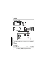
The following table illustrates the connection configuration:
Connections between the Dupline signal and earth potential will cause malfunctions
and are not permissible. In addition, check for the correct polarity of the Dupline signal.
13. Settings
14. Indicators
The LED for movement indication directly is controlled by the Dupline address encoded
at input channel 5. To effectuate a movement indication, this channel must be encoded
to the same address that has been adjusted to channel 1.
Terminal
Description
Terminal
Description
D-
Dupline signal conductor -
D+
Dupline signal con
LED movement indication
Off
If movement is detected, the LED
will not be activated.
On
If movement is detected, the LED
will be activated provided
that the device’s channel 5 has been set to the address of the
movement detection channel (channel 1).
See also chapter 14 “Indicators”.
Prolongation of the movement detection signal
Off
The movement detection signal will not be prolonged.
On
The movement detection signal will be prolonged and depends
on DIP switch 2 (see below) and the rotary potentiometer
„TRANSM. TIMER“
.
The transmission time starts when the initial status of the set
channel changes. Each new activation of the proximity detec-
tor results in its operating time being extended by the preset
value. After this time has elapsed the channel returns to its in-
itial status.
Off
With the rotary potentiometer „TRANSM. TIMER“
the pro-
longation can be set within the range of
12 s ... 2 min
.
On
With the rotary potentiometer „TRANSM. TIMER“
the pro-
longation can be set within the range of
1 min ... 10 min
.
Inverting the movement detection signal
Off
The DBM 1 does
not
invert the alarm signal and switches as
a
normally-open-contact
.
On
The DBM 1 inverts the alarm signal and switches as a
normal-
ly-closed-contact
(sabotage control setting).


