DOEPFER MUSIKELEKTRONIK GMBH
WHEEL ELECTRONIC
(Universal Midi Control Electronics for
Modulation Wheels, Foot Controllers , Breath-
Controller, Joy Sticks etc.)
V1.0 and 2.0
© 2015 by Doepfer Musikelektronik
Page 1: ...DOEPFER MUSIKELEKTRONIK GMBH WHEEL ELECTRONIC Universal Midi Control Electronics for Modulation Wheels Foot Controllers Breath Controller Joy Sticks etc V1 0 and 2 0 2015 by Doepfer Musikelektronik ...
Page 2: ...onsibility with regard to electrical safety and electromagnetic compatibility is up to the user who is assembling the complete device Electronic basic knowledge is required to install WE and to connect the controls resp control voltages If you are not sure whether your knowledge is sufficient please consult an expert We cannot take back modules that became defective because of wrong installation o...
Page 3: ...or other parts A cable set that contains all required connectors and cables is included with WE Carry out all connections in the off state of WE i e when powered off only Do not power on WE i e do not connect the power supply to the corresponding jack socket before all five inputs ST1 ST5 are connected Do not leave analog inputs unconnected Unused inputs have to be connected or jumpered to GND or ...
Page 4: ... range 0 V with V 3 5V is used for measurement This measure is necessary e g for modulation or pitch wheels foot controllers or joy sticks that do not cover the complete angle of rotation If such an element is connected to GND and 5V the maximal output voltage is much less than 5V e g 3V only Even breath controllers e g Yamaha BC 1 2 3 output only about 3 5V maximal voltage If an electronics is us...
Page 5: ...external supply WE can be used any where with a locally purchased power supply thus keeping the retail price down The power supply has to be able to deliver 7 12 VDC unstabilized voltage as well as a minimum current of 100mA WE is switched ON by plugging the AC adapter into a wall outlet and connecting it to the appropriate jack on the WE board There is no separate ON OFF switch After power on the...
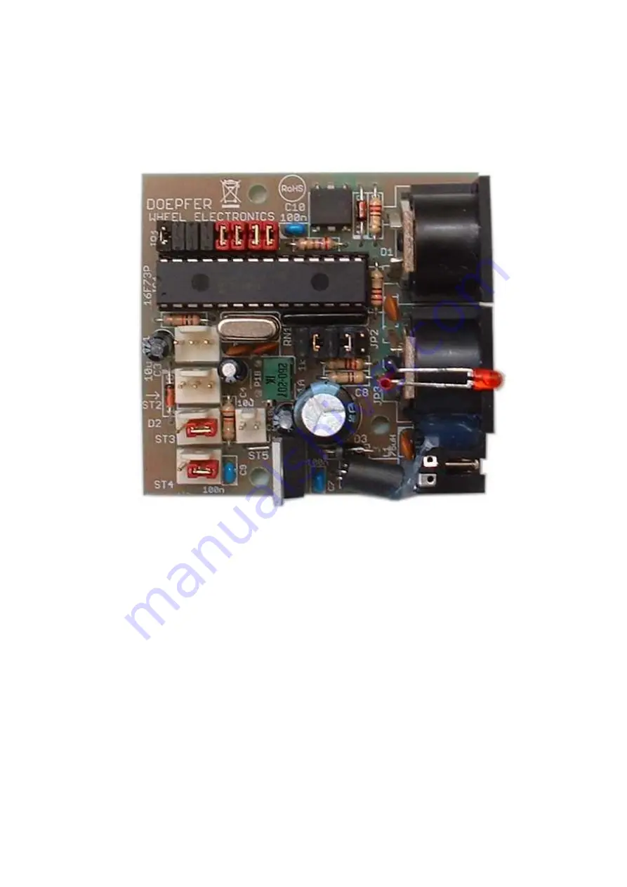
Page 6: ...In BU1 2 Midi Out BU2 5 pin headers for analog controls ST1 ST4 8 jumper area JP1 for adjustment of Midi channel and preset 4 LED control 6 pin header for switching control ST5 7 trimming potentiometer P1 9 jumper area JP2 for voltage range 1 2 3 4 5 8 7 6 5 4 3 2 1 10 jumper area JP4 for the selection of the supply voltage 5V 8V for ST1 ST4 availabe only in version 2 ...
Page 7: ...cted to left GND end terminal 1 of the potentiometer the terminal that corresponds to Midi data 0 center measuring input control voltage center terminal of the potentiometer right 5V end terminal 2 of the potentiometer the terminal that corresponds to Midi data 127 The control voltages are normally generated by rotary or fader potentiometers that are connected between GND and 5V In this case the w...
Page 8: ... the center pin of ST1 ST4 to GND left position or 5V right position Even momentary or toggle switches can be connected to ST1 ST4 altought WE was not developed for this application The switches can be used in two different ways state of rest active state Midi data voltage Midi data voltage version 1 0 0V 127 5V version 2 127 5V 0 0V Simple momentary switches 1 contact open at rest or simple toggl...
Page 9: ...he range of 5V no pressure to 2 5V maximum pressure In addition the behaviour can be adjusted by the trimming potentiometers offset and gain of the BC2 The pinout of the breath controller connector is taken from the service manual of Yamaha BC2 Pay attention to the unusual connection of 5V and GND A BC2 has been tested successfully in combination with WE The specification of the breath control con...
Page 10: ...er area JP1 The jumper area JP1 is made of a double row pin header with 16 pins that can be used to install up to 8 jumpers The jumpers 1 4 are used to adjust the Midi channel With the jumpers 5 8 one of the presets is selected A preset defines the assignments of Midi messages to the analog inputs ST1 ST4 and the switching input ST5 The following table shows the relation between the settings of th...
Page 11: ...ontrol change 67 number other controller number control change number Remarks Preset 1 is the standard preset for pitch bender modulation wheel and two controllers for volume and after touch Preset 2 is similar to preset 1 but after touch is replaced by breath control The WE firmware has been adapted to the Yahama BC2 Provided that the BC2 is wired as described on page 9 it generates a voltage in ...
Page 12: ...the value of the potentiometer is a good starting point Even a trimming potentiometer instead of a fixed resistor can be used If the behaviour is reverse the connections have to be exchanged pull down resistor between GND and the measuring input potentiometer of the foot controller between the measuring input and 5V Even foot controllers with a combination of switches and potentiometers are availa...
Page 13: ...ed to adjust the reduced voltage range V Any voltage between 0V and 5V can be adjusted though only voltages in the range 3 5V should be used Reference voltages below 3V cause malfunction of the analog to digital converters though nothing can be damaged The reduced voltage V becomes valid for an input if the corresponding jumper of JP2 is removed see above table For the adjustment of P1 a small scr...
Page 14: ...inal of the power supply socket for this connection The board measures about 59 x 56 x 25 mm Three mounting holes with 3 mm diameter are available for mounting the board inside the case e g with distance sleeves or spacers 5 mm in length and suitable screws Pay attention that no short circuits are made neither on the top of the board electronic parts nor on the bottom solder points or pcb tracks I...
Page 15: ... short circuit between GND and 5V was made If momentary or toggle switches are used at the analog inputs ST1 ST4 are the 10k 4k7 100k resistors soldered accordingly Are the Midi connections between WE and the other Midi devices installed correctly Midi Out of WE has to be connected to Midi In of the Midi device controlled by WE Especially when computers are used Midi In and Out are very often mixe...
Page 16: ...Doepfer Musikelektronik www doepfer com Doepfer Musikelektronik GmbH Geigerstr 13 D 82166 Graefelfing Germany Tel 49 89 89809510 Fax 49 89 89809511 Email sales doepfer de 2015 by Doepfer Musikelektronik ...