DOEPFER
System A-100
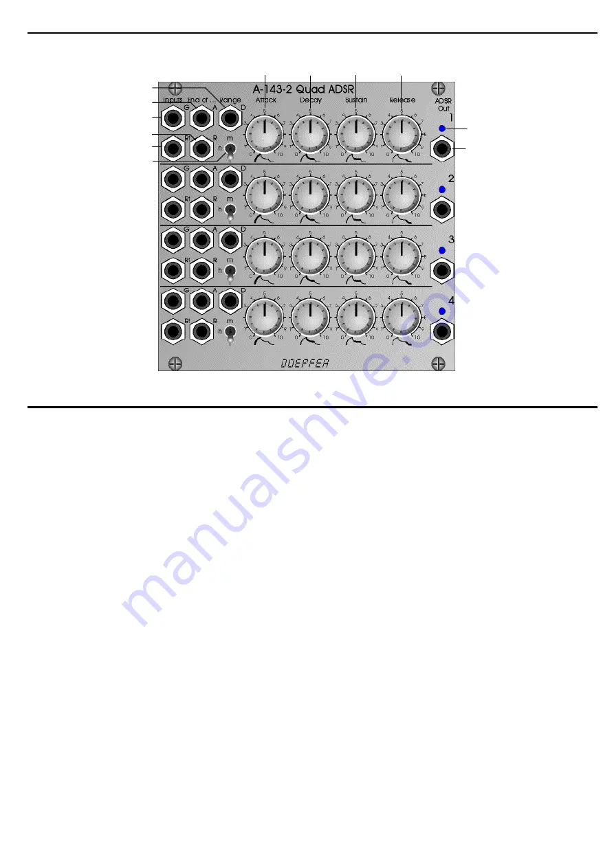
Quad ADSR A-143-2
3
3. Overview
Fig. 5: A-143-2 front panel
1
!
2
4
5
&
6
$
%
"
§
Page 1: ...rns high These outputs can be used e g to daisy chain several ADSR units For this the digital output in question EOA EOD or EOR has to be connected to the Gate input of the following ADSR Even automat...
Page 2: ...decay phase the slope falls to the Sustain level defined by the sustain control with a time adjusted by the decay control At the end of the decay phase the envelope output remains at the sustain level...
Page 3: ...DOEPFER DOEPFER DOEPFER DOEPFER System A 100 Quad ADSR A 143 2 3 3 Overview Fig 5 A 143 2 front panel 1 2 3 4 5 6...
Page 4: ...control 5 Release release control 6 envelope display LED Inputs and Outputs G gate input gate inputs 2 4 are normalled to gate input 1 End of A end of attack output End of D end of decay output Rt ret...
Page 5: ...s 2 3 4 and 5 are used to adjust the attack time the decay time the sustain level and the release time The range switch 1 is used to select one of three time ranges for the time controls attack decay...
Page 6: ...OD of unit 1 is connected to the gate inputs of unit 2 4 and works as a master gate signal The four channel example of A 143 1 can be realized with the A 143 2 as well Cyclically triggered envelope ge...