doble TDR9000 User Manual Download Page 174

Running a First Trip/Close Test: Special Considerations

4-76

72A-1898   Rev. A    11/01

Monday

, November 26, 2001 1:09 pm

To run the test:

1.

Select a test type from the picklist on the upper right corner of the 
window.

2.

Click 

Run XXX Test

 where 

XXX

 designates the type of test.

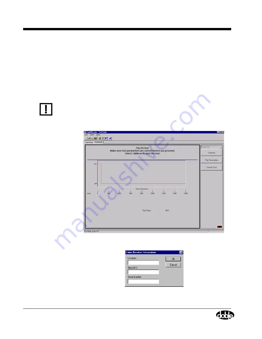
The Virtual Front Panel then appears as shown in Figure 4.49. This 
window displays the values of the configured command parameters 
and allows for confirmation by the operator.

N

OTE

If the fields shown in Figure 4.50 have not been correctly filled in on the 
Test Plan, the Enter Breaker Information window appears. This window 
contains the fields constituting the minimal information required to 
identify a specific breaker in the field. If Special ID is not used, enter 

NONE

.

Figure 4.49  Enable Safety Switch

Figure 4.50  Enter Breaker Information

Summary of Contents for TDR9000

Page 1: ...TDR9000 Circuit Breaker Test System User s Guide Doble Engineering Company 85 Walnut Street Watertown Massachusetts 02472 4037 USA www doble com PN 500 0314 72A 1898 Rev A 11 01...

Page 2: ...ctions as set forth in subparagraphs c 1 and c 2 of the Commercial Computer Software Restricted Rights Clause at FAR 52 227 19 This manual is protected by copyright all rights reserved No part of this...

Page 3: ...H RESPECT TO THE PRODUCT INCLUDING BUT NOT LIMITED TO ANY IMPLIED WARRANTIES OF MERCHANTABILITY AND FITNESS FOR A PARTICULAR PURPOSE DOBLE EXPRESSLY DISCLAIMS ALL WARRANTIES NOT STATED HEREIN IN THE E...

Page 4: ...and workmanship Purchaser may terminate this agreement By returning the software product and all copies thereof in any form and affirming compliance with this requirement in writing DOBLE will refund...

Page 5: ...1 15 Running the Test 1 19 Step 1 Removing Safety Grounds 1 19 Step 2A Running the Self Diagnostic Test Optional 1 19 Step 2B Running the Continuity Test Recommended 1 20 Step 3 Performing the Pretest...

Page 6: ...Functionality 3 5 Tab Navigation 3 5 Configuration Levels 3 7 Connector Indications 3 9 TDR9000 Physical and Virtual Front Panel Numbering 3 12 OCB Motion 3 17 EHV 3 19 Event 3 21 System 3 22 Trip Clo...

Page 7: ...ont Panel 4 30 Configuring Test Plans 4 39 Running Tests 4 69 Removing Safety Grounds 4 69 Using the Pretest Checklist 4 70 Running the Continuity Test 4 71 Running Tests 4 75 Running a First Trip Clo...

Page 8: ...24 O C O Test Parameters A 128 Appendix B Troubleshooting and Parts Replacement B 1 Troubleshooting B 1 Self Diagnostics Test B 1 Troubleshooting Flow Chart B 10 Application and Troubleshooting Proble...

Page 9: ...D 2 Motion Channels D 2 Auxiliary Contact Channels D 2 Analog Channels D 3 Capacitance Channels D 3 Circuit Breaker Control D 3 System Operation D 4 System Startup and Pre Test Configuration D 4 Test...

Page 10: ...AN3 TR3190 Mechanical Interfaces and Other Transducers I 9 Adapters and Transducers I 10 Universal Adapter I 20 AN4 TDR9000 Contact and Resistor Measurement Dynamics I 23 AN6 Velocity Measurements I...

Page 11: ...TRXField Test Plan Partial 1 17 Figure 1 13 Step 4 Virtual Front Panel 1 18 Figure 1 14 Breaker with Safety Grounds Removed 1 19 Figure 1 15 Continuity Test 1 20 Figure 1 16 Continuity Test Results 1...

Page 12: ...5 Figure 4 4 TR3190 TR3160LR Transducer Components 4 16 Figure 4 5 Chuck Holder Plate Configuration 4 17 Figure 4 6 Chuck Holder Plate Mounting to Tighten Rotary Chuck 4 18 Figure 4 7 Chuck Holder Pla...

Page 13: ...gure 4 42 Trigger Output Tab Trigger In set to Aux Contact 4 67 Figure 4 43 Continuity Test Selection 4 71 Figure 4 44 Run Continuity Test 4 72 Figure 4 45 Test Abort Message Switch Release 4 73 Figur...

Page 14: ...ter Arc Chute of a Westinghouse Air Circuit Breaker A 9 Figure A 9 Vacuum Interrupter Schematic A 10 Figure A 10 60 Hz Dielectric Strength of SF6 vs N2 A 11 Figure A 11 Double Pressure SF6 Circuit Bre...

Page 15: ...g Measurement A 40 Figure A 42 Close Timing from Current Measurement A 41 Figure A 43 Close Timing from Voltage Measurement A 42 Figure A 44 Set Contact Channel A 42 Figure A 45 Transition of Contact...

Page 16: ...eration A 69 Figure A 82 Main Contact Timing Open Parameters and Specifications A 70 Figure A 83 Main Contact Timing Open Breaker A 71 Figure A 84 Main Contact Timing Close Breaker A 72 Figure A 85 Ma...

Page 17: ...A 100 Figure A 120 Motion Characteristics for Main Contacts A 101 Figure A 121 Motion Characteristics for Main Contacts Continued A 101 Figure A 122 Main Contact Travel Closed to Part A 102 Figure A 1...

Page 18: ...B 3 Figure B 2 Safety Switch Operation B 4 Figure B 3 Test Abort Message B 4 Figure B 4 Global Self Test B 5 Figure B 5 Local Self Test B 6 Figure B 6 Local Self Test Executing B 7 Figure B 7 Self Te...

Page 19: ...Figure C 27 Version Conflict C 18 Figure C 28 Printers Window C 18 Figure C 29 Pentax PocketJet II Properties C 19 Figure C 30 Pentax PocketJet II Properties Graphics C 19 Figure C 31 Pentax PocketJe...

Page 20: ...i Electric Power Products 100 SFMT SF6 Gas Circuit Breakers I 17 Figure I 15 Mitsubishi Electric Power Products SFMT SF6 Gas Circuit Breakers I 17 Figure I 16 General Purpose Adapter I 18 Figure I 17...

Page 21: ...e 4 9 Keyboard Selections for Precision Cursor Movement 4 91 Table 4 10 Phase Encoded Signal Colors 4 93 Table A 1 Delay Command Parameters A 35 Table A 2 Recording Lengths and Sampling Rate A 55 Tabl...

Page 22: ...H 3 Table H 3 Event Module H 4 Table H 4 Trip Close Module H 5 Table H 5 Trigger In H 5 Table H 6 System Module Signal Characteristics H 6 Table H 7 TDR9000 Physical H 7 Table H 8 TDR9000 Environment...

Page 23: ...anels Describes the TDR9000 Physical and Virtual Front Panels and how they interrelate Chapter 4 Setup and Operation Details the physical installation configuration and use of the TDR9000 Appendix A T...

Page 24: ...0 Appendix E Maintenance Contains procedures for cleaning and general maintenance Appendix F Glossary Contains a description of commonly used terms Appendix G Error Messages Lists the error messages f...

Page 25: ...in the text are shown in this text User entered text Text entered into TRX or TRXField fields is shown in this text Field Names Displayed text Messages displayed on windows and field names are shown i...

Page 26: ...xxii 72A 1898 Rev A 11 01 Monday November 26 2001 1 09 pm...

Page 27: ...Circuit Breaker Preparation 2 TDR9000 Connections 3 Circuit Breaker Connections 4 Laptop and TDR9000 Test Plan Configuration Step 1 Circuit Breaker Preparation NOTE Safety issues are different for Fi...

Page 28: ...r control panel b Close leads across the terminals of the manual Close switch on the circuit breaker control panel Alternately connect the two trip leads between the DC voltage and the trip coil and t...

Page 29: ...Bushing Red A 1 Yellow B 3 Blue C 5 Black COM 2 4 6 Table 1 2 EHV Dead Tank Connections Alligator Clip Color Phase Contact Yellow Red 1 Red Red 2 Black Red COM Yellow Red 3 Red Red 4 Black Red COM Yel...

Page 30: ...Configuration on page 1 15 1 Connect the TDR9000 ground connection to circuit breaker ground 2 Connect a Doble current probe to a CT secondary for each phase being measured to record the Main Contact...

Page 31: ...as the Trigger option and Trigger In set as the trigger source in the Test Plan connect Trigger In cables across the 52CS T contacts for Trip 52CS S contacts for Close Does not have the Trigger option...

Page 32: ...em ground receptacle and ground the other end 3 Plug the Safety Switch cable into the SAFETY receptacle of the System module The Safety Bypass flag is used for First Trip Close tests 4 Ensure that the...

Page 33: ...Circuit Breaker Test System User s Guide 72A 1898 Rev A 11 01 1 7 Monday November 26 2001 1 09 pm Figure 1 2 Step 2 Physical Front Panel for EHV Test Figure 1 3 Step 2 Physical Front Panel for OCB Mot...

Page 34: ...ary Channels on page 4 32 to connect an Auxiliary Contact Refer to Monitoring Analog Channels Current and Voltage on page 4 33 to connect a voltage input Refer to Current Probes on page 4 34 to connec...

Page 35: ...er test no control cable is used Connect to an Event module if using the Aux Contact trigger source and to the Trigger In connectors on the System module if using the Trigger In source Table 1 3 appli...

Page 36: ...els Item Signal Type TDR9000 Module Connection 1 Main Contact A from CT secondary Analog Event 2 Main Contact B from CT secondary Analog Event 3 Main Contact C from CT secondary Analog Event 4 Trip re...

Page 37: ...for the Dead Tank test or in Figure 1 7 on page 1 12 for the Live Tank test 2 Mount the transducer as explained in Rotary Linear Transducer Installation on page 1 14 NOTE During test setups it is impo...

Page 38: ...Cables grounded Motion Transducer Cable Breaker Trip Close Control Cable AC Power Supply Cable TDR9000 Safety Cable Ground Close Close Trip Trip 52CS C 52CS T Breaker Control Circuit in the Control Ca...

Page 39: ...2A 1898 Rev A 11 01 1 13 Monday November 26 2001 1 09 pm Figure 1 8 shows an installation with Live Tank circuit breaker contact monitor cabling in place Figure 1 8 Installation with Circuit Breaker C...

Page 40: ...spectively WARNING When using a linear rod make sure that the circuit breaker is in a safe position before beginning transducer installation A safe position exits when an accidental circuit breaker op...

Page 41: ...n Figure 1 11 shows how the TDR9000 looks once the laptop is set up Figure 1 12 on page 1 17 shows a partial TRXField Test Plan and Figure 1 13 on page 1 18 shows the Virtual Front Panel once the soft...

Page 42: ...Step 4 Laptop and TDR9000 Test Plan Configuration 1 16 72A 1898 Rev A 11 01 Monday November 26 2001 1 09 pm Figure 1 11 Step 4 TDR9000 and PC Wiring PC Wiring PC Wiring...

Page 43: ...TDR9000 Circuit Breaker Test System User s Guide 72A 1898 Rev A 11 01 1 17 Monday November 26 2001 1 09 pm Figure 1 12 Step 4 TRXField Test Plan Partial...

Page 44: ...Step 4 Laptop and TDR9000 Test Plan Configuration 1 18 72A 1898 Rev A 11 01 Monday November 26 2001 1 09 pm Figure 1 13 Step 4 Virtual Front Panel...

Page 45: ...mmended Performing the Pretest Checklist Running a Test Saving Test Results Step 1 Removing Safety Grounds Figure 1 14 shows a breaker with the safety grounds removed from one side of the circuit brea...

Page 46: ...inuity Test window NOTE The Continuity Test must be run with the circuit breaker in the closed position If the Continuity Test fails check all test connections starting with the connections to the cir...

Page 47: ...n Figure 1 16 Figure 1 16 Continuity Test Results Step 3 Performing the Pretest Checklist Use the checklist given in Table 4 8 on page 4 70 to ensure that the system is safely configured for testing t...

Page 48: ...rigger 4 Press the button on the Safety Switch cable until the alarm ceases After test data is collected the test results appear in graphic form Refer to Running Tests on page 4 75 for specific instru...

Page 49: ...TDR9000 Circuit Breaker Test System User s Guide 72A 1898 Rev A 11 01 1 23 Monday November 26 2001 1 09 pm NOTE Autosave disables Save in the File menu and the Save Toolbar icon...

Page 50: ...Step 5 Saving Test Results 1 24 72A 1898 Rev A 11 01 Monday November 26 2001 1 09 pm...

Page 51: ...2 1 shows the TDR9000 in one of its more comprehensive configurations This configuration is used for Live Tank and Dead Tank circuit breaker testing Figure 2 1 TDR9000 Circuit Breaker Test System The...

Page 52: ...and Graphics tabs The TRXField software which operates the TDR9000 has the ability to overlay the results from different tests for comparison The TDR9000 compares Test Results against circuit breaker...

Page 53: ...Probes Mechanical Performance Contact travel and velocity Electrical Performance A Auxiliary contacts status B Current measurement C Voltage measurement Electrical Performance OCB or EHV A Contact sta...

Page 54: ...ary of circuit breaker Test Plans from which an editable circuit breaker specific Test Plan can be created The storage of test data The evaluation of circuit breaker test data from single and multiple...

Page 55: ...ual circuit breaker test graphically and then tailor the presentation of results to highlight behaviors of interest The ability to view the results in a tabular form then toggle back to the Test Plan...

Page 56: ...Ohmic value of pre insertion resistors optional The Motion channels measure the linear or rotary movement of up to six TR3190 3160 motion transducers The software accommodates User defined zones of me...

Page 57: ...oices EHV Measures two breaks per phase on all three phases 6 contacts Split Tests breakers with odd numbers of interrupters per phase or activates and tests one contact at a time in a module Figure 2...

Page 58: ...tors the state of up to three sets of auxiliary contacts Figure 2 6 shows the available configurations for the EVENT module Figure 2 6 Event Module Configurations System The System module is minimally...

Page 59: ...O Reclose O C O C O Trip Close Current Isolation Option The Trip Close module can be outfitted with an optional internal current isolation measurement capability for the Trip and Close control leads W...

Page 60: ...r to operate a circuit breaker using an input generated by the TDR9000 as connected through the Trigger Out connectors of the System module Serial Interface Serial communication is via the electricall...

Page 61: ...ty Empty Empty Empty System Motion OCB or Empty EHV 1 2 Empty Empty Empty System Motion OCB or Empty EHV 1 2 EHV 3 4 Empty Empty System Motion OCB or Empty EHV 1 2 EHV 3 4 EHV 5 6 Empty System Motion...

Page 62: ...cs and Tabulation tabs The contents of both of these tabs can be printed to the optional printer in the field or to a printer in the home office Figure 2 8 through Figure 2 12 on page 2 17 give exampl...

Page 63: ...rcuit Breaker Test Types Test Initial State Intermediate Final State State 1 State 2 Trip O First Trip O Closed Open Close C First Close C Open Closed Reclose O C Closed Open Closed Trip Free C O Open...

Page 64: ...ters exist They are accessed via the Test Plan tab and the test parameters button and are used to determine if a test result tabulation is based on a Timing Event other than Test Initiation Timing Eve...

Page 65: ...iated after the Trip Pulse operates the close circuit and performs the Reclose function Reclose and Delay These parameters determine when the Close Pulse is initiated Standing Initiates a Close 5 cycl...

Page 66: ...of the circuit breaker Trip Free and Delay These parameters determine when the Trip Pulse is initiated Standing Initiates 5 cycles 8 3 ms at 60 Hz after the test starts Delay Initiates after the time...

Page 67: ...nd Delay 1 and Delay 2 These parameters determine when the Close Pulse is initiated Standing Initiates 5 cycles 8 3 ms at 60 Hz after the Trip Pulse The second Trip Pulse occurs measured from the star...

Page 68: ...apacitors These capacitors are located in parallel with the main contacts and can be measured through the EHV modules cables when the contacts are open The test consists of measuring capacitance in th...

Page 69: ...resistor level bounce and close because a CT secondary is used as the signal source instead of the main contact cables since the Main Contacts are energized NOTE Compare the First Trip Close Test Res...

Page 70: ...ent 52 X or Y coil current analog measurement 52 X relay contact state Aux Contact measurement 52 Y relay contact state Aux Contact measurement 52A relay contact state Aux Contact measurement 52B rela...

Page 71: ...interface Types of modules available and the relationship between the physical and virtual front panels Physical and Virtual Front Panel Characteristics Figure 3 1 on page 3 2 shows a TDR9000 Physica...

Page 72: ...3 2 72A 1898 Rev A 11 01 Monday November 26 2001 1 09 pm Figure 3 1 TDR9000 Physical Front Panel Connections B A C E D L M J K H G N F O I...

Page 73: ...na jack connectors for completing general purpose analog measurements voltage current shunt and current probe inputs E Banana jack connector for connecting the shield lead of analog test cables to the...

Page 74: ...ing the modules Figure 3 1 on page 3 2 is powered up The modules that appear on the Virtual Front Panel are dictated by the TDR9000 firmware which polls the TDR9000 Instrument and adds the modules it...

Page 75: ...TRXField Module level vs connector level configuration Understanding connector indications TDR9000 Physical and Virtual Front Panel Numbering Tab Navigation Figure 3 3 and Figure 3 4 show the tabs th...

Page 76: ...d editable When these fields are edited the data displayed on the Tabulation and Graphics tabs change to reflect the effect new parameter settings have on the data gathered during the test This is a u...

Page 77: ...ystem module does not include a module level configuration capability To configure a parameter click the virtual image associated with it Module The module level configures all fields associated with...

Page 78: ...4 contains an OCB connector and a Motion connector This module is effectively split in two with the overall Motion parameters window accessed by clicking Motion on the bottom of the virtual module and...

Page 79: ...nector Indications Figure 3 7 shows an example of an OCB connector with callouts to its various components shown as rings All connectors on the Virtual Front Panel use the same basic functionality whe...

Page 80: ...have a gray center there is no communication between the Instrument and the laptop via the serial port Check the serial port connections Component B is gray when Channels are activated in the Test Pl...

Page 81: ...ndicators flash green when data is being transmitted or received through the communications port of the laptop or computer running TRXField left and right indicators respectively Figure 3 8 Transmit R...

Page 82: ...rstand Physical Front Panel numbering Location and backplane Slot A Physical Front Panel Location denotes where a module is plugged into the TDR9000 Figure 3 9 shows how numbering develops for the TDR...

Page 83: ...backplane slots to operate This explains for instance why once a location is configured for an EHV module an Event module cannot be placed there To change module types when allowed a backplane card o...

Page 84: ...le location is Location 2 EHV modules in Location 2 are referred to as EHV1 EHV modules in Location 3 are referred to as EHV2 and so on Note Ensure that the physical connections completed on the Physi...

Page 85: ...odule functionality A graphic that maps the relationship between the Physical Front Panel and the Virtual Front Panel using the related TRXField Test Plan parameters as a bridge In graphics bracketed...

Page 86: ...s mapping works Figure 3 13 Example Module Mapping Refer to Connecting the TDR9000 Physical Front Panel on page 4 30 for specific configuration procedures Physical Front Panel Virtual Front Panel Test...

Page 87: ...ude three or six motion channels Data can be presented in English or Metric units The TRXField software has the ability to set two user defined zones for the measurement of velocities and to set a ran...

Page 88: ...Monday November 26 2001 1 09 pm Figure 3 14 OCB Motion Module Mapping Physical Front Panel Virtual Front Panel Test Plan Items The Digital Discriminator parameter available only on the Test Plan affec...

Page 89: ...ion choices for the contacts as a group EHV Measures two breaks per phase on all three phases Split Tests circuit breakers with odd numbers of interrupters per phase or activates and tests one channel...

Page 90: ...26 2001 1 09 pm Figure 3 15 EHV Module Mapping Test Plan Items Physical Front Panel Virtual Front Panel EHV or Split selection only on Test Plan The Digital Discriminator parameter available only on t...

Page 91: ...pplications where a current probe is used a probe zeroing process must be completed Refer to Current Probes on page 4 34 Auxiliary Contact Channels The Auxiliary Contact portion of the Event module mo...

Page 92: ...ions connector to the laptop Safety Switch cable input connector AC power supply receptacle System ground connector The System module provides the interface for two optional modules that add to the fu...

Page 93: ...TDR9000 to control the following tests Trip Close Trip Free Standing Trip Free Delay Trip Free Contact 1 Make Reclose Standing Reclose Delay O C O Standing O C O Delay O C O Contact 1 Make This modul...

Page 94: ...ector This option measures the Trip and Close circuit current during a Trip Close test by Shunting the Trip and Close currents through the Trip Close Current component of the Trip Close module Convert...

Page 95: ...01 3 25 Monday November 26 2001 1 09 pm Figure 3 17 maps the relationship between the System physical module and its virtual counterpart for Trip Close operations Figure 3 17 System Module Mapping Tr...

Page 96: ...l The trigger can be one of four types Open to Close Close to Open On to Off Voltage Off to On Voltage Trigger In An input that comes in through the Trigger In connection of the System module and is c...

Page 97: ...idth can be set along with a trigger delay The Trigger Output parameters pertain to only one thing the TDR9000 Trigger Out channel on the System module The Trigger Output is essentially a solid state...

Page 98: ...3 28 72A 1898 Rev A 11 01 Monday November 26 2001 1 09 pm...

Page 99: ...r be energized references to discussions of test setup are found in First Trip Close Tests Once test setup is complete move to Using the Pretest Checklist on page 4 70 and proceed with the rest of the...

Page 100: ...e First Trip Close tests Doble does however recommend finding a spot on the circuit breaker s mechanism and permanently installing a motion transducer while the breaker is de energized For safety reas...

Page 101: ...age 4 65 For each relay contact state measured an Auxiliary Contact channel must be activated given a label and a phase If the relay contact state is measured using a Trigger In channel the Triggers o...

Page 102: ...f channels and a recommended set of channels respectively Since this is an external trigger test no control cables are used Connect to an Event module if using Aux Contact trigger source and to the Tr...

Page 103: ...t of Channels Item Signal Type TDR9000 Module Connection 1 Main Contact A from CT secondary Analog Event D 2 Main Contact B from CT secondary Analog Event 3 Main Contact C from CT secondary Analog Eve...

Page 104: ...le 3 Connect the current probes Doble P N 401 0055 to selected relay coil circuits and then connect the leads to Doble probes and into the Event module Analog channels as required This records the sel...

Page 105: ...an 122 F 50 C Do not store the Instrument or transducers in excessively humid environments Do not expose the Instrument or transducers to rain snow sand or dust Always transport the Instrument or tran...

Page 106: ...be aware of the work activity taking place around them and be alert to the possibility that non test personnel may enter the test area Agree on a consistent and uniform set of visual and verbal signa...

Page 107: ...Grounding considerations include Solidly ground or earth the apparatus under test the TDR9000 and any other external equipment being used When the TDR9000 is permanently housed in a vehicle bind the...

Page 108: ...on to the circuit breaker itself the Contact Monitor cables act as excellent antennae for electrostatic or electromagnetic pickup Since the length of the cables and their relationship to the energized...

Page 109: ...that the circuit breaker is closed WARNING When using a linear rod make sure that the circuit breaker is in a safe position before beginning transducer installation A safe position exists when an acc...

Page 110: ...oved while the mechanism is up In this way if the circuit breaker is activated accidentally the rod can only move down 4 Mount the transducer on the tank All tests on a given circuit breaker can be pe...

Page 111: ...Make sure that one side of each phase is External Ground Connection Contact 1 Phase A Contact 2 Phase B Common Contact 3 Phase C Contact Monitor Cables grounded Motion Transducer Cable Breaker Trip C...

Page 112: ...lists the circuit breaker adapters available Table 4 3 Circuit Breaker Adapters Doble Adapter Circuit Breaker Manufacturer Circuit Breaker Type TR3172 Westinghouse SFA TR3173 GE GE Metalclad Air Magne...

Page 113: ...the status of the circuit breaker For a full discussion of the transducer s Transfer Function see Transfer Function on page A 58 Configuration of transducers is discussed in Linear Transducer and Rot...

Page 114: ...nsducer is used to measure Rotary or Linear motion The setup for each measurement follows NOTE Early shipments of the TR3190 were marked externally as TR3160 but were labeled as model TR3160LR on the...

Page 115: ...prior to inserting the travel rod to perform a linear measurement It includes a metal sheath that covers the Rotary Shaft to ensure that the threads do not come in contact with any foreign objects tha...

Page 116: ...aptive screws 3 Position the wrench portion of the Chuck Holder Plate on the Rotary Shaft see Figure 4 6 4 Thread the Rotary Chuck onto the Rotary Shaft and hand tighten using the Chuck Holder Plate t...

Page 117: ...y November 26 2001 1 09 pm 8 Remove the Chuck Holder Plate from the Rotary Shaft and use the two captive screws to secure it in the ROTARY position on the Transducer Figure 4 7 Configuration is comple...

Page 118: ...Figure 4 6 on page 4 18 4 Rotate the Rotary Chuck counterclockwise and remove it from the Rotary Shaft Utilize the Chuck Key if necessary as described in step 6 of the previous procedure 5 Store the...

Page 119: ...TDR9000 Circuit Breaker Test System User s Guide 72A 1898 Rev A 11 01 4 21 Monday November 26 2001 1 09 pm Figure 4 8 Chuck Holder Plate Mounted in LINEAR Position Version 1 Version 2...

Page 120: ...of the TR3160 which differ only in the design of the Rotary Adapter mechanism The TR3160 model has the Rotary Adapter shown in Figure 4 9 and is configured using the following procedures The TR3160LR...

Page 121: ...minder that it must be removed prior to inserting the travel rod to perform a linear measurement NOTE If the Rotary Chuck requires tightening tighten while using the locking pin to hold the Rotary Sha...

Page 122: ...he hexagonal opening in the face of the transducer and align the three captive screws refer to Figure 4 11 on page 4 24 2 Tighten the captive screws Configuration is complete Figure 4 11 Rotary Adapte...

Page 123: ...ed to configure the TDR9000 Virtual Front Panel follows After each step a cross reference leads to the specific discussion of that topic Once all required tasks from this general procedure are complet...

Page 124: ...s a basis Refer to Connecting the TDR9000 Physical Front Panel on page 4 30 4 Configure the Virtual Front Panel If an item is not configurable via the Virtual Front Panel return to the Test Plan tab t...

Page 125: ...out conflicts between the software version being run on the laptop and the firmware version on the Instrument If a conflict exists the laptop unless cancelled by the user downloads its version of the...

Page 126: ...de of the printer parallel interface cable to the LPT1 port of the laptop 5 Connect the power source for the printer There are two power sources provided with the printer Rechargeable battery Instruct...

Page 127: ...ield icon shown below or select Start Program Files Doble TRX TRXField The firmware polls the Instrument to detect the modules present and the window shown in Figure 4 15 on page 4 40 appears At this...

Page 128: ...ons refer to Figure 4 13 on page 4 30 NOTE Not all connections are required for all tests For First Trip Close tests wiring connections refer to Configuring Analog Auxiliary Channels for First Trip Cl...

Page 129: ...end assuring a secure and reliable connection See H in Figure 4 13 on page 4 30 3 Plug the Safety Switch cable into the SAFETY receptacle of the System module If using an external trigger use the Saf...

Page 130: ...o connect an OCB Contact Monitor cable to the OCB connector on the TDR9000 OCB Motion module and then to the appropriate circuit breaker bushings See A in Figure 4 13 on page 4 30 Connect alligator cl...

Page 131: ...Current probe input Current shunt input Voltage Monitor The Analog Channels accept voltage inputs up to 300 V peak Configuration is performed using the Analog Channel Connector or the Analog Channels...

Page 132: ...obe the PC running the Virtual Front Panel might not be visible therefore the TDR9000 Instrument creates a modulated beep which aids in properly zeroing the probe When the probe is at zero for two sec...

Page 133: ...e tone becomes steady If zero offset is maintained for two seconds the tone stops and the channel indicator turns green Figure 4 14 Figure 4 14 Probe Zero Indicator g Repeat this procedure for any add...

Page 134: ...polarity sensitive Make sure to attach the shield green yellow banana plug to the chassis ground green yellow banana jack on the Event module b Plug the free end of the Analog cable into the current...

Page 135: ...utton remains red and the following error message appears Process incomplete Probe not zeroed Pressing OK removes the error message leaving the Probe Zero button red 2 Leave the probe on and securely...

Page 136: ...nal block For best results Doble recommends that the shunt be installed on the low or neutral side of the circuit through which the test current flows System Module Trigger In Out Setup The Trigger In...

Page 137: ...Library Test Plan to Breaker Test Plan This occurs by entering information into any of the following fields Manufacturer Serial Number Location Special ID Both Test Plan types minimize the time requi...

Page 138: ...ting plan One of the following buttons is selected Opens the Open window Figure 4 16 on page 4 41 where an existing Test Plan is selected Each active channel is populated with its test plan dictated v...

Page 139: ...g the Virtual Front Panel If this option is selected the modules and channels detected are added to the Virtual Front Panel with default values in place It is then necessary to configure each channel...

Page 140: ...Customer Service email customerservice doble com Figure 4 17 Power Up Diagnostics If the TRXField software detects that a channel designated for use is not supported or that a Test Plan field is confi...

Page 141: ...meant to show the two tabs that appear at this time on TRXField Test Plan and TDR9000 NOTE The Test Plan tab is the default tab It is not possible to move to any other tab until the Model Number is en...

Page 142: ...2001 1 09 pm Figure 4 20 shows a Virtual Front Panel that has an OCB three Motion channels two EHV modules each module has two breaks phase and three phases six Analog and six Auxiliary channels Trip...

Page 143: ...e CONTACT1 as shown in Figure 4 20 Figure 4 21 OCB Contacts The following items are configurable In use A checkbox that activates or deactivates the associated channel Label A user entered field for e...

Page 144: ...e 4 22 and Figure 4 23 on page 4 48 show the Motion Channels and Motion Connector windows respectively The Motion Channels window configures items specific to individual channels as well as items appl...

Page 145: ...nto two groups Motion Channels 1 3 Motion Channels 4 6 The selections described below apply to these groups Transducer Type A picklist for choosing the transducer type Linear Rotary NOTE Selecting Rot...

Page 146: ...ng the phase associated with the channel Configuring the EHV Module Figure 4 24 and Figure 4 25 on page 4 51 show the EHV and the EHV Connector windows respectively The EHV window configures items spe...

Page 147: ...act 2 checkbox Refer to Main Contact Configuration EHV SPLIT Contact Channel Activation on page A 64 for a description Capacitance Two checkboxes per connector one for each contact to activate the TDR...

Page 148: ...on any EHV module sets the range for all EHV modules in that TDR9000 If there is no pre insertion resistor in parallel with the contact the default resistor range None is used If the value of the resi...

Page 149: ...as explained for individual EHV channels above Configuring the Event Module The Event module is comprised of six sets of virtual connectors Three analog measurement connectors that are independently c...

Page 150: ...choices are 2 V 2 V 10 V 300 V 20 A Current Probe 200 A Current Probe Current Shunt 200 mV Current Shunt 2 V Current Shunt 10 V Phase A scrollable picklist for selecting the phase associated with the...

Page 151: ...appears Figure 4 28 Auxiliary Channels Collective The following items are configurable In use A checkbox that activates or deactivates the associated channel Label A field for entering the name associ...

Page 152: ...through the appropriate trigger connector The configuration of each is discussed in the sections that follow Serial Communications The communications port for the serial communications is configured u...

Page 153: ...is present Figure 4 31 Trip Close with Trip Close Current Option Click the virtual Trip Close connector shown in Figure 4 31 to access the T C Current Selection window shown in Figure 4 32 This window...

Page 154: ...nclude 100 A 20 A 5 A 2 A Close Current A scrollable picklist for selecting Close circuit range Choices include 20 A 5 A 1 A 0 2 A NOTE To maximize the resolution for all range selections use the lowe...

Page 155: ...st type Test types include Trip O Close C Reclose O C Trip Free C O O C O First Trip O First Close C Slow Close C Continuity Capacitance Self Diagnostics Once a test type XXX is selected two operation...

Page 156: ...s Tab Trigger Input Refer to page 4 64 Trigger Output Refer to page 4 66 The Trip Parameters window Figure 4 37 is used to explain functionality The Trigger Input and Trigger Output windows are the sa...

Page 157: ...by discussions of its components NOTE If the combination of values entered in these fields is operationally invalid when the OK button is clicked a Test Parameters dialog box appears describing the c...

Page 158: ...asurements in time or in cycles E A Trip Command field where the Trip duration is input or changed This is then displayed in item A F A Close Command field where the Close duration is input or changed...

Page 159: ...Pulse Timing on page A 37 The Delay Type picklist determines whether a Standing Delay or Contact 1 Make is used Table 4 4 Close Test Timing Functions Timing Event Selection Timing Trigger Picklist Ava...

Page 160: ...icklist Each recording length has a sampling rate associated with it When a length is selected the sampling rate appears on the window next to the picklist Table 4 6 lists the Recording Lengths and th...

Page 161: ...ce a test without it K A Signal Viewer functionality button that is used to restore both the Trip Command or Close Command graph once they have been closed Right click anywhere on the Parameters windo...

Page 162: ...are to initiate a test in response to input from the safety switch NOTE Selecting None Internal requires the use of the safety cable Selecting either external trigger input type requires the use of th...

Page 163: ...er Source The number of channels available depends on the number of Event modules in the TDR9000 Pre Trigger This user entered field sets the length of time in ms or cycles prior to a triggering event...

Page 164: ...on the Parameters tab except the Recording Length are disabled and it appears as shown in Figure 4 40 Figure 4 40 Trigger In Activated Trigger Output Tab Trigger outputs may be configured for all test...

Page 165: ...TDR9000 Circuit Breaker Test System User s Guide 72A 1898 Rev A 11 01 4 67 Monday November 26 2001 1 09 pm Figure 4 41 Trigger Output Tab Figure 4 42 Trigger Output Tab Trigger In set to Aux Contact...

Page 166: ...dition Polarity Active Closed only Trigger Delay This user entered field sets the length of time between the start of the test and when the trigger is set NOTE A negative time value for Trigger Delay...

Page 167: ...test can be run ground connections must be removed from either side of the circuit breaker Certain electrical physical conditions however may dictate which safety grounds can safely be removed Refer t...

Page 168: ...A Safety Ground cable is installed on the TDR9000 Proper AC power is available One end of each phase of the circuit breaker is grounded Not applicable to First Trip Close tests All cables are connect...

Page 169: ...pment setup is complete and before any other test is run The Test Results shown in Figure 4 8 on page 4 70 include the channel label and a Pass Fail indication whose text format is configured on the T...

Page 170: ...8 Rev A 11 01 Monday November 26 2001 1 09 pm 2 Click Run Continuity Test The Run Continuity Test window appears Figure 4 44 Figure 4 44 Run Continuity Test 3 Click Continue Once the test data is load...

Page 171: ...y Switch is not pressed within 60 seconds the test is aborted and the window shown in Figure 4 45 appears If the Safety Switch is released before the alarm ceases the test is aborted and the window sh...

Page 172: ...successfully completed the Continuity Test Results window appears Figure 4 48 The active channels are listed along with a Pass Fail designation Figure 4 48 Continuity Test Results If the Continuity Te...

Page 173: ...rrent probe measuring the Trip relay coil current to measure the Close relay coil current Change the Auxiliary Contact label in the Test Plan from 52CS T to 52CS C Move the Aux Contact channel cables...

Page 174: ...as shown in Figure 4 49 This window displays the values of the configured command parameters and allows for confirmation by the operator NOTE If the fields shown in Figure 4 50 have not been correctl...

Page 175: ...from the TDR9000 NOTE For externally triggered tests perform the action to activate the trigger and skip step 4 4 Press the button on the Safety Switch cable until the alarm ceases WARNING This is the...

Page 176: ...rors During a Capacitance test a Capacitance Error dialog box may appear Figure 4 52 Figure 4 52 Capacitance Testing Error If this occurs click one of the buttons ReTest to start the test over after f...

Page 177: ...ollection Status NOTE Data collection times vary depending on the types and number of channels in use This process can take several minutes If the Safety Switch is not pressed within 60 seconds the te...

Page 178: ...ata collection is complete the TRXField software presents the information by switching to the Graphics tab Figure 4 56 shows a sample graphical result NOTE Capacitance Test results do not include grap...

Page 179: ...comparison in the graphical format To work with the Test Results If a test has just been run the Test Results appear as shown in Figure 4 56 Once a test is run the Overlay Graphics File menu item beco...

Page 180: ...used and manipulated however the Signal Viewer program is in use and the display properties of this program are accessible for configuration When viewing test results they appear in graphical form Fig...

Page 181: ...er s time or skill level does not permit a detailed examination of a graphical display Figure 4 59 Tabulation Tab Partial View Graphics Tab The Graphics tab using the Overlay function gives a detailed...

Page 182: ...channel values 1 Move the cursor to determine the value of the channel at different points in time If both cursors are active the difference between the two is also displayed in yellow When channels a...

Page 183: ...s in a state of change at the time shown and the selected sample time contained instances of the circuit breaker in the Resistor and Closed states O R Indicates the contact was in a state of change at...

Page 184: ...tion of the channels 1 Display the channels 2 Ensure that the cursors are turned off If they are on click the Cursor Delete button 3 Click the upper left corner of the channel area to be enlarged and...

Page 185: ...tab To overlay Test Results 1 Select Overlay Graphics from the File menu The Overlay Graphics file selection window appears Figure 4 62 Figure 4 62 Overlay Graphics File Selection 2 Navigate to the de...

Page 186: ...iginal Test Result is available for viewing alone in graphical format or in tabulated format however overlaid Test Results can only be viewed graphically by using the Overlay Graphics tab It is also p...

Page 187: ...el and the Overlay icon appears 5 Release the mouse button The two channels are now overlaid in the same channel frame TRXField automatically selects different colors for each Channel Viewing Properti...

Page 188: ...more chosen points The time appears in the bottom right corner of the data screen The channel values appear to the right of each channel Facts about cursors include Precisely positioning the cursors d...

Page 189: ...8 Precision moves can be made using the keyboard as described in step 4 The keyboard acts on the active cursor only The Cursor Delete button indicates whether the active cursor is the primary green or...

Page 190: ...gnal Viewing Properties window appears Figure 4 64 Figure 4 64 Signal Viewing Properties The following checkboxes can be selected Use signal frame ticks Adds a tiny vertical tick under each vertical v...

Page 191: ...that with five or more circuit breakers a comparison of channels among different circuit breakers is more necessary than a comparison of different channels associated with the same circuit breaker Aut...

Page 192: ...gnal Viewing Properties Advanced Window NOTE Doble recommends that these defaults remain unchanged Using the Edit Specs Tab The Edit Specs tab appears once the test is run This tab contains all the fi...

Page 193: ...t Breaker Test Plan Both types of files fit onto a floppy disk and should be loaded into the TRX software database in the home office for storage for further use or in the case of Test Results for com...

Page 194: ...st Results from the Test Plan or TDR9000 tab 1 Click Save on the File menu The Specify File Type window appears as shown in Figure 4 67 Figure 4 67 Specify File Type Window 2 Select the type of save t...

Page 195: ...and makes locating the file more difficult Closing Without Saving If the Close icon on the upper right of the TRXField window is clicked before a save is completed the following sequence of events occ...

Page 196: ...in Figure 4 70 Figure 4 70 Specify File Type Window 2 Select the type of save to perform Click the TDR9000 button The window shown in Figure 4 66 on page 4 95 appears Follow the procedure for saving...

Page 197: ...ile and makes locating the file more difficult At this time if the Close icon on the Choose Test Plan or Result Destination window is clicked the dialog box shown in Figure 4 72 appears Figure 4 72 Fi...

Page 198: ...st Results of an existing test open the desired plan using the instructions given in Connecting the TDR9000 Physical Front Panel on page 4 30 and then print using the procedure above This requires tha...

Page 199: ...o OFF NOTE Disconnect the cables from the circuit breaker end first 2 Disconnect the Doble current probe from the CT secondary phases 3 Disconnect Doble current probes from the selected relay coil cir...

Page 200: ...Disconnecting After the Test 4 102 72A 1898 Rev A 11 01 Monday November 26 2001 1 09 pm...

Page 201: ...tion moves away from the stationary contact the arc stretches This stretching and cooling enables the arc to quench at a point where the current is zero t2 B in Figure A 1 subsequent to contact partin...

Page 202: ...ast Circuit Breakers Air Magnetic Circuit Breakers Figure A 2 and Figure A 3 on page A 4 explain the process that occurs for current interruption in an Air Magnetic Circuit Breaker The distinctive fea...

Page 203: ...Terminal De energized Breaker in closed position Arc Chute 1 Main Contacts separate 2 Arcing contacts separate 3 Arc transfers to runners This inserts Main Contacts Arcing Contacts Components shown in...

Page 204: ...ir Magnetic Breaker Operation Continued 6 Small arcs are attached into loops 7 Current is interrupted Visible break 5 Arc transfers to splitters to form This cools the arc and increases resistance to...

Page 205: ...rcuit Breaker Operation 1 Cross section of a circuit breaker showing 2 The trip coil is energized and releases a 3 Air blast continues to force air past the 4 When the air travels and streams alongsid...

Page 206: ...normal conditions current carrying conductors are surrounded by compressed air is used in circuit breakers rated up to 765 kV 5 As the air blast continues the energy 6 The arc is extinguished at the...

Page 207: ...mbers are filled with compressed air Compressed Moving Decompressed Atmospheric On opening the moving contact in the main chamber is actuated the blast valves open and release air from the chamber thu...

Page 208: ...il This process continues throughout the arcing period at intervals of the order of tens of microseconds though these time intervals are not constant because the relevant events both inside and outsid...

Page 209: ...parison between a Westinghouse 10 cm diameter vacuum interrupter rated 500 MVA 15 kV 22 kA and the arc chute of a Westinghouse Air Circuit Breaker of comparable rating Reprinted from Reference 2 Permi...

Page 210: ...contact surfaces The metal vapor continually leaves the intercontact region and recondenses on the contact surfaces and the surrounding metal vapor condensation shield The shield is usually isolated...

Page 211: ...graph demonstrating the dielectric strength of SF6 and N2 Reprinted from Reference 2 Permission granted by Marcel Dekker Inc Figure A 10 60 Hz Dielectric Strength of SF6 vs N2 At any given pressure th...

Page 212: ...Circuit breakers Its operation is similar in principle to that of Air Blast Circuit Breakers It is comprised of mainly a high pressure metal reservoir where most of the SF6 is kept and an interrupter...

Page 213: ...me gas pressure about 5 atm while the circuit breaker is closed When the circuit breaker is being opened the contacts separate and an arc is drawn between them The heat generated by the arc heats the...

Page 214: ...ied in 765 kV range Figure A 13 Puffer Type SF6 Circuit Breaker Operation The SF6 gas in the cylinder is compressed by the downward movement of the cylinder and is forced into the nozzle area where th...

Page 215: ...the live tank design as shown in Figure A 15 the circuit breaker interrupters are mounted in a container at line potential and are insulated from ground potential using porcelain insulating columns T...

Page 216: ...right subsystem VR t stress the recently conducting arc plasma The transient recovery voltage TRV is defined as the difference between the voltage on the left and right sides of the circuit breaker F...

Page 217: ...ing current flows through R This must be interrupted subsequently by opening the auxiliary interrupter S1 The primary use of the resistors in modern circuit breakers is to reduce voltage transients on...

Page 218: ...ltage Shunt Resistor Operation Open Gap Grading Capacitor Figure A 19 shows how an open gap grading capacitor is used to modify the TRV courtesy of Mitsubishi Electric A capacitor is applied across th...

Page 219: ...ole operators are used in most circuit breakers above 345 kV When a high voltage circuit breaker consisting of three single pole operators is used Independent Pole Operation it is necessary to employ...

Page 220: ...quired Circuit switchers employ SF6 vacuum or other types of interrupters to break a circuit and either the interrupter or the knife blade to make the contact Models with more than one gap can utilize...

Page 221: ...is still open The final closing of the blade activates the mechanism closing the interrupter Some circuit breakers have isolators 6 Figure A 21 in conjunction with their main interrupting contacts 1 F...

Page 222: ...ys a typical circuit used to monitor contact status Figure A 22 Contact Monitoring Both Main contact and resistor switch open To another measuring module Main contact open Resistor Switch closed Both...

Page 223: ...rator depends on the relationship between inputs as shown on Figure A 23 Figure A 23 Voltage Comparator Output Figure A 24 shows how changing the contact assembly status both open Main Contact open re...

Page 224: ...round present in each Circuit Breaker head Additional capacitance is added by the measurement cables attached to the circuit breaker Figure A 25 shows C1 C2 C3 as the total capacitances to ground pres...

Page 225: ...When contact 2 closes the potential at point A goes from Vs to zero Consequently to simplify the analysis replace the closing of contact 2 with a voltage source which represents a step down function...

Page 226: ...rroneous contact state transition information Although it is desirable to distinguish between real contact activity and cross coupled signals with 2 s resolution this is neither a practical nor realis...

Page 227: ...ement and the second through electrical measurement The value of contact penetration is obtained as follows with the circuit breaker closed a mark is made on the moving contact as shown in Figure A 28...

Page 228: ...t Plan Dynamics The main body of this guide explained the procedures for operating the TDR9000 including the mechanics for creating or using existing Test Plans This section describes the effect that...

Page 229: ...appears Open An Open window appears from which existing Test Plans or Test Results are opened Refer to Tab Navigation on page 3 5 for more information Save A Specify File Type dialog box appears and...

Page 230: ...ientation Automatically prints graphics in landscape format Test Plans and Tabulated format Test Results are printed in portrait format Default Test Recording Length Sets the user preferred length for...

Page 231: ...Rev A 11 01 A 31 Monday November 26 2001 1 09 pm 1 Access the TRX Options window by Selecting TRX Options from the View menu or Clicking the Options button Figure A 32 TRX Options 2 Modify the settin...

Page 232: ...he Test Plan parameters for editing Open the Properties window Select the language in which the Test Plan appears NOTE Portuguese is under development Save Changes is available once the Test Plan is m...

Page 233: ...recommends that all the Required parameters be entered Figure A 35 Nameplate Parameters Required Information NOTE The location model number and manufacturer lists are contained in the Location tab Mo...

Page 234: ...ptional Information Command Parameters Figure A 36 shows the Command Parameters Figure A 36 Command Parameters Inst Book Number User specified fields for entering additional breaker information Mech N...

Page 235: ...ed Delay 1 Length sets the time for a first test condition to be implemented Delay 2 Length sets the time for those tests where it is applicable such as an O C O test for a second test condition to be...

Page 236: ...selected as a base for the second cycles conversion NOTE The Timing Frequency is set on the TDR9000 Virtual Front Panel or from the TRX Options window opened from the TRXField View menu Delay Trip Com...

Page 237: ...out and de energize the coil The trip pulse is 66 6 ms at 60 Hz 80 ms at 50 Hz Select a trip pulse length that is long enough to allow the A switch to de energize the trip coil Close Pulse Timing The...

Page 238: ...Hz 160 ms for 50 Hz Figure A 38 shows how timing works for test initiation The times t1 and t2 indicate the following t2 The time required to close the Main Contact The close time is measured from th...

Page 239: ...ntage of full scale current of the range selected and is adjustable in 10 increments The selection made calculates the timing of the Main Contact t2 and resistor switch t1 Figure A 40 on page A 40 aft...

Page 240: ...ll not record any time in the tabulations Figure A 40 Close Timing from Close Current Measurement Analog Current Voltage Magnitude Timing a close test based on current voltage magnitude for a particul...

Page 241: ...current selected for that channel Figure A 42 if the T0 option is selected in Resistor Switch Timing Close on page A 77 The measurements in Figure A 42 were calculated using an external current probe...

Page 242: ...the full scale selected for that channel if the T0 option is selected in Resistor Switch Timing Close on page A 77 Figure A 43 Close Timing from Voltage Measurement AUX Contact Transition Timing a Clo...

Page 243: ...ers C O The close pulse and the delay length are adjustable in 1 10 ms increments 1 2 Cycle The following options are available for the trip initiation command Standing Delay Contact 1 Make Standing T...

Page 244: ...tion Delay The trip pulse is applied after the specified time delay 0 0 to 1600 ms and continues for the duration of the test Figure A 48 Figure A 48 Trip Free Delay The delay length default value is...

Page 245: ...the duration of the test Figure A 50 Figure A 50 Trip Free Contact 1 Make Figure A 51 shows how the Trip is started when Contact 1 makes a first pulse touch Figure A 51 Trip Free Contact 1 Make Operat...

Page 246: ...If the 1 2 cycle delay must be eliminated the reclose test with the delay option set to 0 0 ms should be used Figure A 52 Reclose Standing Figure A 53 shows how the Standing Close command is delayed...

Page 247: ...the command pulse To maintain plan compatibility these limits are maintained for the TDR9000 The following options are available for the close command initiation Standing Delay Contact 1 Make Standin...

Page 248: ...o the circuit breaker delayed by a specified time interval Delay 1 Length after the initiation of the trip command The second trip command is applied to the circuit breaker that is delayed by a specif...

Page 249: ...ms 66 6 ms Figure A 59 shows how the O C O Delay works Figure A 59 Reclose Trip Delay Operation Contact 1 Make A trip command of a specified duration is applied to the circuit breaker at time zero Fig...

Page 250: ...delay default value is 66 6 ms 55 ms 121 6 ms Figure A 61 shows how the O C O Delay works Figure A 61 O C O Contact 1 Make Operation If the delays for any of the options described are selected improp...

Page 251: ...63 The Trip Close module is not used for this test The trigger can be one of four types Open to Close Close to Open Volts On to Volts Off Volts Off to Volts On Figure A 63 AUX Contact Trigger Paramete...

Page 252: ...Either Or conditions Open to Closed or On to Off Use this setting to detect a transition either from Open to Close or Volts On to Volts Off Closed to Open or Off to On Use this setting to detect a tra...

Page 253: ...ng Data Collection This is available for both the AUX Contact and Trigger In test It is the length of time in ms or cycles prior to a triggering event for which data is retrieved This pre trigger data...

Page 254: ...ystem trigger input Trigger Out cannot be used with Event Triggers like Aux Contact Trigger input When used with Internal triggering Trip Close control the delay can be either positive or negative A p...

Page 255: ...from a picklist Each recording length has a sampling rate associated with it When a length is selected the sampling rate appears below it Table A 2 lists the Recording Lengths and their associated sam...

Page 256: ...creen can be edited and phase A to B or C can be selected Figure A 66 Motion Channel Parameters Transducer Type Either Linear or Rotary motion can be selected Measurement units can be English Metric o...

Page 257: ...igure A 67 Linear Motion Measured in English or Metric Figure A 68 Rotary Motion Measured in Degrees If the measurement units are changed after specifications have been entered the Instrument automati...

Page 258: ...the Instrument to see Main Contact motion primary motion The Transfer Function is where numbers relating the transducer connecting rod travel to the Main Contact travel are entered when they are not t...

Page 259: ...vement of the Transducer connecting rod the Main Contacts would move 0 00375 Consequently when the Transfer Function 3 1 is used the resolution becomes 0 00125 x 3 0 00375 Practical considerations lim...

Page 260: ...on for the chosen default value The transducer wheel has a circumference of 5 Consequently if the Main Contact travel is such that the transducer wheel makes a full turn 360 deg the rod pressing again...

Page 261: ...FA Circuit Breaker when the Main Contacts travel 8 05 the rotation at the rotary input of the transducer is 35 5 deg Figure A 73 Figure A 73 Rotary To Linear Transfer Function This corresponds to a li...

Page 262: ...tion resistors set a resistor value range in the Test Plan for the program to pick up the resistor level for the time during which the resistor is in the circuit during circuit breaker operation and f...

Page 263: ...or the actual current applied the current recorded in the masthead reads Over The current on the graphical output appears clipped The performance of the test is not affected Figure A 75 Figure A 75 Br...

Page 264: ...sting a Live Tank Circuit Breaker with an odd number of breaks per phase EHV Resistor Ranges Trip Close For circuit breakers with insertion resistors set a resistor value range in the Test Plan for th...

Page 265: ...ll for the actual current applied the current recorded in the masthead reads Over The current on the graphical output appears clipped The performance of the test is not affected Figure A 77 Figure A 7...

Page 266: ...s presented as a pass fail rating based on whether each measurement is within the Test Plan limits Figure A 78 shows the parameters available for the Capacitance channels Figure A 78 Capacitance Chann...

Page 267: ...act Channels Figure A 79 Auxiliary Contact Channel Parameters and Specifications Auxiliary Contacts Channel Activation This portion of the Test Plan activates and labels the contact channels for auxil...

Page 268: ...ween probe and shunt Table A 5 lists the selections available It is important to select appropriate matching current ranges on the TDR9000 and on the probe itself The recommended probes are Autozero p...

Page 269: ...output to 2 V The Instrument has two current ranges to use with the probe Low 20 A High 200 A The following example shows how inappropriately selected current ranges can give misleading test results...

Page 270: ...s to Vout Vout 6 12 10 0 612 V This voltage is interpreted by the TDR9000 on the 20 A scale as 2 V corresponds to 20 A 0 612 V corresponds to I2 I2 0 612 x 20 2 6 12 A Contact Timing Parameters Figure...

Page 271: ...allowable difference in time between the opening of the two Main Contacts in any module Phase B The maximum allowable difference in time between the opening of any two Main Contacts in a phase Breake...

Page 272: ...nce in time between the closing of the two Main Contacts in any module Phase B The maximum allowable difference in time between the closing of any two Main Contacts in a phase Breaker C The maximum al...

Page 273: ...in time between the Trip initiation and the closing of the two Main Contacts in any module Phase B The maximum allowable difference in time between the Trip initiation and the closing of any two Main...

Page 274: ...max The maximum time the Main Contacts may be CLOSED during a Trip Free test Figure A 86 shows the Trip Free Dwell Time Figure A 86 Trip Free Dwell Time Reclose Dead Time parameters include Reclose D...

Page 275: ...ch Timing Open The selection can be made using the Resistor Relative To parameter between MAIN and T0 Test Initiation This enables the timing of Resistor Switches relative to the opening of the Main C...

Page 276: ...r switches in any module Phase B The maximum allowable difference in time between the opening of the two resistor switches in a phase Breaker C The maximum allowable difference in time between the ope...

Page 277: ...enables the timing of Resistor Switches relative to the closing of the Main Contacts or test initiation Parameters include Minimum The minimum time for the Resistor Switches to make Maximum The maximu...

Page 278: ...y module Phase B The maximum allowable difference in time between the closing of the two resistor switches in a phase Breaker C The maximum allowable difference in time between the closing of the two...

Page 279: ...acceptable NOTE First touch is considered first strike for a close test and last break for an open test Different values of resistor tabulation qualifiers are needed to accommodate the characteristics...

Page 280: ...resistor switch tabulation without the necessity of having a resistor level present for any minimum amount of time The default value is 200 s Figure A 93 and Figure A 94 give examples that clarify the...

Page 281: ...stor Switch timing from the beginning of the test t 0 The Main option tabulates resistor switch timing relative to the closing first strike or opening last break of the Main Contact For further inform...

Page 282: ...od or Rotary Adapter travel if the Transducer Connecting Rod or Rotary Adapter and Main Contact travel are identical Transfer Function is 1 Contact Wipe Close This is the distance the Transducer Conne...

Page 283: ...t Contact Monitor Cable 1 to phase A Set the Expected Plus and Minus specifications in the Contact Wipe parameter portion of the Travel Specifications on the Test Plan tab Figure A 96 Contact Wipe Mea...

Page 284: ...reaker Main Contacts beyond the final open position Negative tolerance for overtravel must never be greater than the specified overtravel Rebound This is the distance between the maximum temporary dis...

Page 285: ...final closed position Negative tolerance for overtravel must never be greater than the specified overtravel Rebound The distance between the maximum temporary displacement of the Circuit Breaker Main...

Page 286: ...Specifications Average Velocity Open The velocity zone must be entered before the test for the velocity in that zone to be calculated by the Instrument There are five methods of specifying the zone f...

Page 287: ...e greater than the start distance FROM NOTE When selecting values for calculating Average Velocity avoid choosing beginning or ending distances of 0 000 in mm Since the circuit breaker remains in thos...

Page 288: ...t and the specified time after that moment For an Oil Circuit Breaker Figure A 104 if only one transducer is used the Instrument uses the Main Contact data for the phase where the motion channel is ac...

Page 289: ...Circuit Breaker s Average Velocity is calculated for the interval between when the Main Contacts part and the point in time that corresponds to the specified distance Figure A 106 on page A 90 shows t...

Page 290: ...ntact 2 Contact 3 To Distance Phase where the motion channel is activated and the Transducer is installed phase B Final Open Position Zone 1 From Contact Open Starting Closed Position start of test Mo...

Page 291: ...culated by the Instrument There are five methods of specifying the zone for Average Velocity measurements during a close test Distance Distance Distance Time Time Time Time Contact Close Distance Cont...

Page 292: ...breaker Figure A 116 on page A 97 In Figure A 109 the end distance T0 must be less than the start distance FROM Figure A 109 Contact Close Distance Distance Distance Time The Circuit Breaker Average...

Page 293: ...ent when the Main Contacts make and the time specified before the make Figure A 112 For the Oil Circuit Breaker if only one transducer is used the Instrument uses the Main Contact data for the phase o...

Page 294: ...igure A 113 Figure A 113 Contact Closed Time Contact Close EHV Circuit Breaker Module 1 Module 1 Module 2 Module 1 Module 2 Module 2 2 3 4 2 3 4 Contact 1 Contact 2 Contact 3 Contact 4 0A 0C 0 20 40 6...

Page 295: ...ulated for the period between the moment when the Main Contacts make and the time specified before the make Figure A 114 Figure A 114 Contact Closed Time Contact Close Oil Circuit Breaker Final Closed...

Page 296: ...ure A 115 Figure A 115 Contact Closed Time Contact Close EHV Circuit Breaker Module 1 Module 1 Module 1 Module 2 Module 2 2 3 4 2 3 4 Contact 1 Contact 2 Contact 3 Contact 4 0A 0C 0B Starting Open Pos...

Page 297: ...fail determination for each measurement corresponding to a limit that was set in the Test Plan This section shows both Breaker Performance Reports and their associated graphical results Important topi...

Page 298: ...of the origination of important results Live Tank Breaker This discussion covers the characteristics for a Live Tank Circuit Breaker test whose report is shown in Figure A 117 A See Digital Discrimin...

Page 299: ...ls 1 3 Trip Operation Section Continued MECHANICAL MOTION CHANNELS 1 3 TRIP OPERATION Specifications Test results Compare Average velocity in Open zone 1 Maximum 32 80 Ft Sec VEL 1 35 40 Ft Sec Fail M...

Page 300: ...tions are shown in Figure A 120 and Figure A 121 and the graphical results are shown in Figure A 122 on page A 102 and Figure A 123 on page A 103 C The difference in time between the opening of the tw...

Page 301: ...0 5 Phase A Phase B Phase C Contact Time Compare Contact Time Compare Contact Time Compare mS mS mS A EHV 1 B EHV 1 C EHV 1 A EHV 2 0 1 Pass B EHV 2 0 2 Pass C EHV 2 0 0 Pass Specs Delta Main Contact...

Page 302: ...Rev A 11 01 Monday November 26 2001 1 09 pm D This is the distance that the Main Contacts travel from the close position baseline to the point where they part last break Figure A 122 Figure A 122 Main...

Page 303: ...1898 Rev A 11 01 A 103 Monday November 26 2001 1 09 pm E This is the Average Velocity measured during the period from 500 s before and 400 s after Main Contacts part Figure A 123 Figure A 123 Main Con...

Page 304: ...0 0 B EHV 1 C EHV 1 A EHV 2 B EHV 2 C EHV 2 A EHV 3 B EHV 3 C EHV 3 A EHV 4 B EHV 4 C EHV 4 Specs Resistor Switch Opening Time Measured From Test Initiation Maximum Minimum Phase A Phase B Phase C Co...

Page 305: ...Vs Mechanical Motion Phase A Phase B Phase C Contact Travel Vel Contact Travel Vel Contact Travel Vel deg d s deg d s deg d s A EHV 1 20 6 899 B EHV 1 C EHV 1 A EHV 2 B EHV 2 C EHV 2 A EHV 3 B EHV 3...

Page 306: ...1 01 Monday November 26 2001 1 09 pm B This is the distance the Resistor Switches travel from the close position baseline to the point where they part last break Figure A 126 Figure A 126 Resistor Swi...

Page 307: ...ev A 11 01 A 107 Monday November 26 2001 1 09 pm C This is the Average Velocity measured during the period from 500 ms before and 400 ms after the Resistor Switches part Figure A 127 Figure A 127 Resi...

Page 308: ...pecifications for voltage and current monitoring A These are the peak values for each voltage and current waveform monitored during circuit breaker operation that are tabulated B This is the time of t...

Page 309: ...User s Guide 72A 1898 Rev A 11 01 A 109 Monday November 26 2001 1 09 pm Dead Tank Circuit Breaker Figure A 129 and Figure A 130 on page A 110 show the report for a Dead Tank Trip Test Figure A 129 De...

Page 310: ...contact triggers the timing of the Main Contacts which happens to be 15 3 ms after test initiation Figure A 133 on page A 113 This is useful when timing specifications are based on close coil energiz...

Page 311: ...TDR9000 Circuit Breaker Test System User s Guide 72A 1898 Rev A 11 01 A 111 Monday November 26 2001 1 09 pm Figure A 131 Dead Tank Breaker Close Tabular Report A...

Page 312: ...A EHV 2 0 2 Pass B EHV 2 0 2 Pass C EHV 2 0 0 Pass Specs Delta Main Contact Closing Time Within a Phase Maximum 2 0 Phase A Phase B Phase C Contact Time Compare Contact Time Compare Contact Time Comp...

Page 313: ...Channels 4 6 Phase A Phase B Phase C Contact Travel Vel Contact Travel Vel Contact Travel Vel in f s in f s in f s A EHV 1 6 281 12 29 B EHV 1 6 199 12 40 C EHV 1 6 289 12 40 A EHV 2 6 311 11 88 B EH...

Page 314: ...01 Monday November 26 2001 1 09 pm C This is the distance the Main Contacts travel from the fully open position to the first make Figure A 134 Figure A 134 Main Contacts Time Fully Open to First Make...

Page 315: ...ev A 11 01 A 115 Monday November 26 2001 1 09 pm D This is the Average Velocity measured during the period from 500 ms before and 400 ms after Main Contacts make Figure A 135 Figure A 135 Average Velo...

Page 316: ...ta Time for Resistor Switches in a Module Specs Insertion Resistor Duration Time Maximum 9 0 Minimum 5 0 Phase A Phase B Phase C Contact Time Compare Contact Time Compare Contact Time Compare mS mS mS...

Page 317: ...esistor Switch Closing Time Within the Breaker Maximum 2 0 mS Breaker 1 2 mS Pass Resistor Switch Closing Time Vs Mechanical Motion Channels 1 3 Phase A Phase B Phase C Contact Travel Vel Contact Trav...

Page 318: ...e the Resistor Switches travel from the fully open position to the first make Figure A 139 Figure A 139 Resistor Switches Time Fully Open to First Make Contact Ohms Compare Contact Ohms Compare Contac...

Page 319: ...A 11 01 A 119 Monday November 26 2001 1 09 pm C This is the Average Velocity measured during the period from 500 ms before and 400 ms after the Resistor Switches make Figure A 140 Figure A 140 Averag...

Page 320: ...Test Report Refer to Trip Free Parameters C O on page A 43 for more information on these parameters A Delay 1 Length is shown in Figure A 145 on page A 123 Delay 1 is 8 3 ms if Standing option is used...

Page 321: ...rip Free Test Operation for a Phase Live Tank Breaker Within the phase the Dwell time Figure A 144 on page A 122 is measured as the difference between the time required for the first Main Contact to o...

Page 322: ...ase C 32 5 Pass Trip Free Dwell Time Within the Breaker Specifications Test results Compare Breaker 34 0 mS Pass Main Contact Closing Time Measured From Test Initiation Specifications Test results Tra...

Page 323: ...age Velocity Zone in trip operation for example if the zone is defined by distance distance or distance time this velocity is not tabulated for trip free operation Figure A 145 Trip Free Test Mechanic...

Page 324: ...he Breaker test report for a Reclose test Refer to Reclose Parameters O C on page A 45 for more information on these parameters Figure A 146 Dead Tank Breaker Reclose Test Report Header A Dead Time Th...

Page 325: ...the time required for the last Main Contact to close and the first Main Contact to open B Dead Time with a Circuit Breaker This is the time when at least one Main Contact within the circuit breaker is...

Page 326: ...Specifications Test results Compare Maximum 333 0 mS Phase A 315 6 mS Pass Minimum 250 0 Phase B 315 7 Pass Phase C 316 6 Pass Reclose Dead Time Within the Breaker Specifications Test results Compare...

Page 327: ...a Reclose Test Specifications Test results Compare Average velocity in Open zone 1 Maximum 15 50 Ft Sec Ft Sec Minimum 12 60 VEL 2 13 66 Pass Zone 1 0 250 in to 6 500 in Average velocity in Open zone...

Page 328: ...rough Model Number FK 121 43000 4 Circuit Serial Number 0202A9405 701 Operator Instr Book Mechanism TP CREATED 8 9 99 Mech Instr BY PHIL PROUT Special ID Westborough Operation Counter Test Type O C O...

Page 329: ...wcharts A Problem Solution table A drawing from the top view of the circuit boards that comprise the system Interpreting TDR9000 LEDs Self Diagnostics Test The Self Diagnostics test is comprised of th...

Page 330: ...ircuit board module level The Self Diagnostics test simulates a circuit breaker test without activating the Trip or Close output signals During this test hardware circuitry provides test signals that...

Page 331: ...st NOTE This test can be run with cables connected to the Instrument 1 Click Self Diag from the test picklist on the upper right corner of the TDR9000 tab The Run Self Diag Test button appears on the...

Page 332: ...el modules The system is armed and the window prompts for the Safety Switch to be pressed as shown in Figure B 2 Figure B 2 Safety Switch Operation 5 Press the Safety Switch and hold until the alarm c...

Page 333: ...s shown in Figure B 4 The first test run is the Global Self Test A status bar appears as the TDR9000 collects data about the validity of source signals on the Physical Front Panel This test requires s...

Page 334: ...Switch must be pressed within 60 seconds Figure B 5 Local Self Test 6 Press the Safety Switch until the alarm ceases Once this second part of the test begins the window appears as shown in Figure B 6...

Page 335: ...ure B 6 Local Self Test Executing A status bar appears as results are calculated If a failure is found a window appears containing the slot or location of the failed circuit board or module a part for...

Page 336: ...ion Transducer receiver results Contact timing and resistor timing measurement Analog and Auxiliary contact status There is no way to directly print this data however it can be saved using the Save bu...

Page 337: ...connectors and if the connectors appear to be OK try reseating the board NOTE It is possible that failure in a Physical Front Panel module may cause the same symptom as in the first bullet If the LED...

Page 338: ...ing Flow Chart The flow charts shown in Figure B 9 on page B 11 and Figure B 10 on page B 12 assist in troubleshooting TDR9000 operations They start from TDR9000 trouble indications LEDs non operation...

Page 339: ...d at the same time Cable In Bits Failure on page B 9 Replace P S assembly Power Supply on page B 26 No Contact Doble B Yes Check LED on Reseat or Not Steady Steady Green VFP Virtual Front Panel Is the...

Page 340: ...TDR9000 2 Verify that all circuit board LEDs are green Figure B 12 on page B 16 3 Verify D8 and D18 LEDS are blinking green Replace any circuit board where LED is off or red Verify with Doble the ver...

Page 341: ...eturn to Doble for repair Spilled liquid penetrates the Instrument case Return to Doble for repair A test is run breaker functions properly but no Main Contact data is collected or data for a contacts...

Page 342: ...wer is ON Printer is not jammed Refer to Pentax documentation provided with the Instrument Connections on Virtual Front Panel appear gray Check the Connection between the laptop and the Instrument Com...

Page 343: ...A 1898 Rev A 11 01 B 15 Monday November 26 2001 1 09 pm TDR9000 Top View Figure B 11 and Figure B 12 on page B 16 show a generalized internal top view drawing of the TDR9000 Figure B 11 Top View of TD...

Page 344: ...isible through the oval cut into the top of the circuit board housing Figure B 11 on page B 15 These LEDs indicate circuit board operation as follows All circuit board LEDs change from Off to Green or...

Page 345: ...ence the communications loopback LED should illuminate This LED is viewed by looking through the handle vent opening nearest the System module on an angle from the back of the Instrument to the front...

Page 346: ...ED on the System module Physical Front Panel that indicates proper operation of the power supply as shown in Figure B 14 Figure B 14 DC Power Supply LED If this LED is not lit when power is applied us...

Page 347: ...ce only complete printed circuit boards or other subassemblies None of the solid state printed circuit boards need user calibration or adjustment Remove or insert printed circuit assemblies carefully...

Page 348: ...red to perform the replacement Table B 2 lists the ribbon cables that need to be disconnected by circuit board type Table B 2 Required Cable Disconnects by Circuit Board Circuit Board Type Replaced Ca...

Page 349: ...it board 9 Ensure the replacement board is fully seated by pressing down on the center of the card bracket 10 Tighten the captive screws on the circuit board 11 Reconnect any circuit board ribbon cabl...

Page 350: ...nel NOTE The System Front Panel module is not replaceable in the field If troubleshooting analysis indicates a problem or failure is related to this module contact Doble Customer Service Also it is ne...

Page 351: ...ting Inserting two banana clip leads into two connectors on the module face of an Event module and gently pull while rocking the module side to side 4 Align the connector on the replacement module wit...

Page 352: ...System module Physical Front Panel that indicates proper operation of the power supply as shown in Figure B 16 Figure B 16 DC Power Supply LED Table B 4 Replaceable Physical Front Panel Module Part N...

Page 353: ...he internal temperature of the Instrument is too high or the monitoring circuit is bad To access the power supply module and examine the fuses 1 Turn the TDR9000 power off and unplug 2 Unscrew the two...

Page 354: ...R9000 6 Check the LED on the System module Physical Front Panel If LED is not green refer to the Troubleshooting Flow Charts starting on page B 11 7 Replace the top cover and reinstall the two rubber...

Page 355: ...assembly 6 Insert the replacement assembly into the guides and gently push it into position 7 Replace the cables disconnected in step 4 8 Plug the unit in and power up the TDR9000 9 Check the LED on t...

Page 356: ...es fuses or the final high current stage of the module NOTE Before running this test run the Continuity test on the EHV or OCB cables If a test is run and no errors are reported and the circuit breake...

Page 357: ...p pair Run a simple test e g Trip Close If both the Trip and Close control pulses are seen on the contact channels graphs the TDR9000 is OK The problem is outside the Instrument If one or both of the...

Page 358: ...but the suspect cable from the TDR9000 Physical Front Panel The connector on the Virtual Front panel for the cable being tested should be green indicating the channel is ready 3 Clip the circuit break...

Page 359: ...2 cable 25 feet 05B 0620 01 OCB cable 60 feet standard 020 0127 01 through 04 EHV cable set Specify module number 05B 0621 EHV cable individual specify module number and phase 05B 0634 01 through 03 A...

Page 360: ...Service If possible have the Instrument setup near a telephone to facilitate telephone assistance Call Doble Engineering Customer Service at 617 926 4900 or e mail customerservice doble com Please ha...

Page 361: ...ervice for a nominal charge Doble Part 903 0044 The Instrument may be packed using either of the following methods 2 wall minimum corrugated cardboard box with a minimum 2 inch thick poly foam padding...

Page 362: ...B 34 72A 1898 Rev A 11 01 Monday November 26 2001 1 09 pm...

Page 363: ...ing firmware Updating the Pentax printer drivers Updating Software To upgrade the TRXField software 1 Insert the TRXField CD ROM into the correct drive 2 Proceed to Step 11 if autorun is working Step...

Page 364: ...ntents of the drive appear in the Browse window 6 Browse to the Disk1 folder 7 Click setup exe 8 Click Open The Run window reappears with the directory path added as shown in Figure C 3 Figure C 3 Run...

Page 365: ...stallation is C Program Files Doble TRX This should not be changed 12 Click Next A status bar appears as the TRXField files are copied to the hard drive A dialog box appears as shown in Figure C 5 If...

Page 366: ...d not be changed as they overwrite any existing TRX folder 14 Click Next The Choose Desktop Preference window appears 15 Click Yes to add a TRXField icon to the desktop No to proceed to the next windo...

Page 367: ...laptop version of the software to the TDR9000 If permission is Given the download requires approximately five minutes to complete Not given the TDR9000 is disabled for the remainder of the TRXField se...

Page 368: ...dows NT This driver needs only to be loaded once Once the driver is loaded refer to Printer Settings on page C 18 to explain the procedure for tailoring the printer settings to those recommended by Do...

Page 369: ...uit Breaker Test System User s Guide 72A 1898 Rev A 11 01 C 7 Monday November 26 2001 1 09 pm 4 Double click Add Printer The Add Printer Wizard window appears as shown in Figure C 8 Figure C 8 Add Pri...

Page 370: ...8 72A 1898 Rev A 11 01 Monday November 26 2001 1 09 pm 5 Click Next A second Add Printer Wizard window appears as shown in Figure C 9 Figure C 9 Add Printer Wizard II 6 Click the Local Printer radio b...

Page 371: ...Rev A 11 01 C 9 Monday November 26 2001 1 09 pm A third Add Printer Wizard window appears as shown in Figure C 10 Figure C 10 Add Printer Wizard III 7 Click Have Disk The Install From Disk window appe...

Page 372: ...2 Figure C 12 Open 9 Select the A drive from the Drives picklist 10 Click OK and OEMSETUP INF is added to the File Name field 11 Click OK The Install From Disk window reappears 12 Click OK The Add Pri...

Page 373: ...ovember 26 2001 1 09 pm 13 Click Next A fifth Add Printer Wizard window appears as shown in Figure C 14 Figure C 14 Add Printer Wizard V 14 Ensure that LPT1 is selected and click Next A sixth Add Prin...

Page 374: ...page once installation is complete NOTE A Version Conflict window may appear similar to the one in Figure C 16 It is recommended that the newer version of a file be kept by clicking Yes Figure C 16 V...

Page 375: ...ember 26 2001 1 09 pm 3 Click Printers from the Settings menu on the Windows Start menu bar The Printers window appears as shown in Figure C 17 Figure C 17 Printers 4 Double click Add Printer The Add...

Page 376: ...My Computer radio button is selected Click Next A second Add Printer Wizard window appears as shown in Figure C 19 Figure C 19 Add Printer Wizard II 6 Click the LPT1 checkbox Click Next A third Add Pr...

Page 377: ...The Install From Disk window appears as shown in Figure C 21 Figure C 21 Install From Disk 8 Click Browse The Locate File window appears as shown in Figure C 22 Figure C 22 Locate File 9 Select the A...

Page 378: ...window shown in Figure C 23 appears with two versions of the Pentax PocketJet II driver added to the Printers list Figure C 23 Add Printer Wizard IV 13 Click Pentax PocketJet II Roll Paper and then c...

Page 379: ...s as shown in Figure C 25 Figure C 25 Add Printer Wizard VI 15 Ensure that the Not Shared radio button is selected and click Next NOTE A dialog box may appear as shown in Figure C 26 If this occurs in...

Page 380: ...clicking Yes Figure C 27 Version Conflict A status bar appears as the files are copied Printer Settings The procedure that follows explains how to make the Doble recommended modifications to the Penta...

Page 381: ...001 1 09 pm 2 Right click the Pentax PocketJet II icon The Pentax PocketJet II Properties window appears as shown in Figure C 29 Figure C 29 Pentax PocketJet II Properties 3 Click the Graphics tab and...

Page 382: ...utton 5 Click the Advanced tab and the window appears as shown in Figure C 31 Figure C 31 Pentax PocketJet II Properties Advanced 6 Click the No Feed Mode radio button 7 Enter 200 in the No Feed Mode...

Page 383: ...ifferent front end However all channels are collected and forwarded to the controller for processing in the same manner Data processing creates measurements that are compared to specifications circuit...

Page 384: ...oble motion transducers The transducers output two quadrature signals generated from optical sensors which switch on and off based on a picket fence of lines passing between the sensors and a light so...

Page 385: ...est no waveform is sent through the system Circuit Breaker Control The system can be configured with a Trip Close module capable of activating the control coils of the circuit breaker under test The c...

Page 386: ...ge settings for the appropriate channels and the signal on which to trigger the recording Appropriate action by the operator including the pressing of the Safety Switch turns on all of the test voltag...

Page 387: ...ly test the operation of all measurement channels No Trip or Close command signals are output from the Instrument during the Self Diagnostic test Once the test is initiated from the Virtual Front Pane...

Page 388: ...D 6 72A 1898 Rev A 11 01 Monday November 26 2001 1 09 pm...

Page 389: ...cks If in doubt check the electrical rating label attached to each unit Do not for any reason cut or remove the grounding prong from the power cord Turn power OFF and disconnect from line power before...

Page 390: ...d for cleaning electrodes electrical components or moving parts Disconnect the Instrument s power cord and all other external cables before cleaning or removing the Instrument cover Changing Printer P...

Page 391: ...r pulls it into the starting position the situation can be corrected as follows If the printer does not print immediately open the release cover as far back as it goes Pull the paper out reinsert it a...

Page 392: ...E 4 72A 1898 Rev A 11 01 Monday November 26 2001 1 09 pm...

Page 393: ...to be slow in tripping or an out of service breaker to be slow in closing By connecting the TDR9000 to the in service breaker phase currents trip and close coil currents DC battery supply and auxilia...

Page 394: ...F 2 72A 1898 Rev A 11 01 Monday November 26 2001 1 09 pm...

Page 395: ...sts channel activation cross check error messages that occur when there is a TDR9000 connected which indicate the Test Plan cannot be used with the specific TDR9000 connected The error message appears...

Page 396: ...on module required Please deactivate motion channel d More than d analog channels are active in the test plan but the TDR9000 does not have a fourth event module Please deactivate all analog channels...

Page 397: ...or instructions on how to disconnect a cable There must be a safety switch connected in order to control the circuit breaker under test Analog channel d is set to a current probe range but the current...

Page 398: ...s are on motion channels d and d Please change one of the labels s so that all motion labels are unique Duplicate labels are on velocity channels d and d Please change one of the labels s so that all...

Page 399: ...test Remove the safety switch and insert the external trigger plug Table G 5 Test Exceptions Error Message Solution There must be a safety switch connected in order to control the circuit breaker unde...

Page 400: ...ptions Procedure Trip module relay closed before power applied during test run This indicates a problem with the trip close module See Test Exceptions Procedure Close module relay closed before power...

Page 401: ...r service There must be an external trigger plug connected in order to run an externally triggered test Remove the safety switch and insert the external trigger plug N A There must be a safety switch...

Page 402: ...o 1600 0 ms Invalid delay 1 length entered Value must range from 8 0 to 600 0 ms Invalid delay 2 length entered Value must range from 8 0 to 600 0 ms The combination of delay 1 length and delay 2 leng...

Page 403: ...B Motion module Table H 1 OCB Motion Module Characteristic Description OCB Main Contact Channels 3 channels with 1 break per phase Contact Sense Voltage for Main Contact Timing 48 15 7 5 VDC Modified...

Page 404: ...Accuracy 0 1 of measured value 0 1 max error Display Resolution 0 002 Velocity 50 ft sec max Acceleration 1200g for 50 sec max Rotary Transducer Range 0 2880 Resolution 0 09 Display Resolution 0 1 Acc...

Page 405: ...Main Contact Timing 15 7 5 VDC Modified by pre insertion resistor value Contact Sense Voltage for Resistor Switch Timing 15 7 5 VDC Modified by pre insertion resistor value Close and Open Timing Reso...

Page 406: ...e Sampling Frequency 10 kHz Voltage Measurement Range 300 DC AC peak Analog Signal Bandwidth DC to 5 kHz Amplitude Accuracy 0 5 of full scale 0 5 of reading 0 5 of full scale 1 5 of reading for the 30...

Page 407: ...s Table H 4 lists the characteristics of the Trip Close module Table H 5 list the characteristics of the Trigger In function Table H 4 Trip Close Module Characteristic Description Trip Close Peak Volt...

Page 408: ...e Signal Characteristics Characteristic Description Trip Close Command Pulse Width 8 0 to 1600 msec 0 5 to 96 cycles Resolution 0 1 msec 0 1 cycle Trip Command Current Range 2 5 20 100 A Close Command...

Page 409: ...act molded flame retardant ABS Meets National Safe Transit Association testing specification No 1A for immunity to severe shock and vibration Dimensions 10 0 H x 16 0 W x 15 5 D 25 4cm x 40 6cm x 39 4...

Page 410: ...Environmental Specifications Table H 8 lists TDR9000 environmental specifications Table H 8 TDR9000 Environmental Characteristic Description Storage Temperature Range 25 C to 70 C Operating Temperatu...

Page 411: ...R3190 transducer is used to measure the position and velocity of the operating mechanism of a circuit breaker This transducer consists of a reference disk of known diameter which is directly coupled t...

Page 412: ...The motion plot is produced by plotting the sum of the displacement data vs time The delta displacement for each sample interval represents the total displacement which has occurred during the sample...

Page 413: ...The pipe coupling short nipple floor flange assembly is screwed on in place of the cap After this adapter is screwed on to the breaker the connecting rod is then installed and the transducer is clampe...

Page 414: ...rotation of the transducer during circuit breaker operation must be provided To do this a length of 2 x 2 angle is clamped to the transducer and to a suitable part of the circuit breaker structure Ca...

Page 415: ...m to ensure no interference occurs when the breaker operates Large forces are generated when a breaker is operated do not stand in line with the motion of the connecting rod or allow loose parts near...

Page 416: ...ndensing atmosphere Contaminates Transformer Oil Accuracy is unaffected by oil adhering to the connecting rod Contaminates Soil Accuracy is unaffected by dirt adhering to the connecting rod Mechanical...

Page 417: ...aker Test System User s Guide 72A 1898 Rev A 11 01 I 7 Monday November 26 2001 1 09 pm Figure I 1 shows the assembly drawing for the TR3190 Figure I 1 TR3190 Linear Motion with Rotary Chuck Attached T...

Page 418: ...1898 Rev A 11 01 Monday November 26 2001 1 09 pm Also available is the TR3170 Transducer Figure I 2 a scaled down version of the TR3190 Transducer which is designed for linear use only Figure I 2 TR3...

Page 419: ...R3190 was born AN2 TR3190 Digital Linear Rotary Motion Transducer on page I 1 describes the design of the TR3190 Digital Rotary Linear Transducer in detail and provides insight into the design of adap...

Page 420: ...supplied with the SFA Adapter Figure I 3 Westinghouse SFA SF6 Gas Circuit Breaker Figure I 4 shows the Doble ABB AHMA 4 8 Transducer for use with the ABB SF6 Gas circuit breakers using the AHMA 4 or...

Page 421: ...Gas circuit breakers using the AHMA 4 or AHMA 8 operating mechanism It is shown with the drive fork engaging the optical encoder assembly and the gauge block in front of the transducer The gauge block...

Page 422: ...cer and is attached to the rotating element of the phase The disc that drives the semaphore remains with the rotary element The transducer support plate is then attached to the transducer using 5 16 b...

Page 423: ...r is attached to the rotating mechanism and then to the support plate The support plate is the clamped to the structural plate in the cabinet using C clamps Figure I 7 ABB HPL SF6 Gas Circuit Breaker...

Page 424: ...nto a tapped hole in the top of the large metric bolt The transducer is then centered on the travel rod and clamped to the spacer Figure I 9 HVB SF6 Gas Circuit Breakers with Independent Pole Operatin...

Page 425: ...ser s Guide 72A 1898 Rev A 11 01 I 15 Monday November 26 2001 1 09 pm Figure I 10 General Electric Metalclad Air Magnetic Circuit Breakers 600 and 1200 Figure I 11 General Electric Metalclad Air Magne...

Page 426: ...BI Vacuum Circuit Breaker Figure I 13 shows an adapter transducer combination that measures travel at the bellcrank assembly where operating rod travel perpendicular to contact travel is changed to tr...

Page 427: ...binet Figure I 14 Mitsubishi Electric Power Products 100 SFMT SF6 Gas Circuit Breakers Figure I 15 shows the large L shaped plate that replaces the standard bottom plate on the TR3160 Transducer using...

Page 428: ...a close nipple a coupler and a reducer Figure I 16 General Purpose Adapter Figure I 17 shows a general purpose spacer that is used where it is difficult or impossible to mount the transducer directly...

Page 429: ...m User s Guide 72A 1898 Rev A 11 01 I 19 Monday November 26 2001 1 09 pm Figure I 17 General Purpose Spacer Figure I 18 shows various clamps used to temporarily secure the transducer to a fixture Figu...

Page 430: ...r Live Tank Circuit Breakers One of possible positions is rotating shaft of the operating mechanism or the shaft at the phase housing Using the rotary motion at the shaft and the linear motion at circ...

Page 431: ...ng allows axial misalignment and transfers rotary motion 6 Connect the threaded bar with the flexible coupling and chuck at the rotary transducer and tighten the two set screws The transducer with the...

Page 432: ...el at 5 of a cycle after contact part is a minimum of 3 4 from the fully closed position The contact travel at 9 of a cycle after contact part is less than 5 3 from the fully closed position Close to...

Page 433: ...Guide 72A 1898 Rev A 11 01 I 23 Monday November 26 2001 1 09 pm AN4 TDR9000 Contact and Resistor Measurement Dynamics Figure I 21 shows a schematic for the TDR9000 contact and resistor measurement Fi...

Page 434: ...Universal Adapter I 24 72A 1898 Rev A 11 01 Monday November 26 2001 1 09 pm Figure I 22 explains contact and resistor timing Figure I 22 Contact and Resistor Time Diagram...

Page 435: ...nce for all distance measurements is the fully closed position of the circuit breaker and the displacement value for the fully closed position is zero When the transducer rod passes the selected begin...

Page 436: ...e Transfer Function provides the correction factor necessary for these measurements These two values are entered by the user from data provided by the circuit breaker manufacturer and or the user the...

Page 437: ...as necessary A second set of leads sense channel provided this function and enabled timing from that reference point on the trace Since the TDR9000 uses its solid state control circuitry to initiate o...

Page 438: ...n to Main Contact operation is tabulated and given in the Test Results Report AN8 Simultaneous Energization of Two Sets of Trip Coils in a Single Circuit Breaker Many modern high voltage circuit break...

Page 439: ...closing coil observing lead polarity Select Analog as the timing event and enter the channel number in the Timing Channel Prior to closing coil energization the Instrument considers the closing coil...

Page 440: ...les end Table I 3 lists the voltages used for EHV and OCB channels for the TDR9000 AN11 Sampling Rates The basic concept for digital sampling is that the sampling rate should be faster than the event...

Page 441: ...an asynchronous event with respect to the instruments sample period higher sampling rates minimize these errors AN13 Safety Grounds Close Connected Transformers and the Use of the TDR9000 OCB Dead Tan...

Page 442: ...I 32 72A 1898 Rev A 11 01 Monday November 26 2001 1 09 pm...

Page 443: ...xiliary channel connections 4 62 Auxiliary Contact Channel Specifications A 66 Auxiliary Contacts Channel Activation A 67 Auxiliary Wet Dry Contact Monitor I 29 Average Velocity Open A 86 Average Velo...

Page 444: ...g E 2 Close Current Magnitude A 39 Close Test General explanation 2 14 Timing Functions 4 51 Close Timing A 37 Command Parameters A 34 Contact Measurement general A 22 Contact Penetration general A 27...

Page 445: ...Hardware Conflict Errors G 1 Event module General explanation 2 7 Specific explanation 3 21 Virtual Front Panel configuration 4 41 External Triggers Virtual Front Panel configuration 4 56 F Firmware u...

Page 446: ...A 27 L Laptop and TDR9000 Test Plan Configuration general 1 7 Laptop connections 4 27 Linear and rotary attachments installation 4 16 Live Tank test connections 4 15 Live Tank vs Dead Tank operation A...

Page 447: ...A 85 Rebound Open A 84 P Packing the TDR9000 B 33 Parameters Virtual Front Panel configuration 4 46 Pass Fail tabulation text A 30 Physical Front Panel Analog channels connections 4 62 Auxiliary chan...

Page 448: ...f Zeroing Probe 4 65 SFA Adapter I 10 Shunt Capacitor operation A 18 Signal Viewer 4 81 Site Preparation Analog and Auxiliary Setup general 1 13 Circuit Breaker Preparation for Off Line Testing genera...

Page 449: ...act and Resistor Measurement Dynamics I 23 Disconnecting after a test 4 99 4 100 Maintenance E 2 OCB Dead Tank Contact Monitors use I 31 Packing for return B 33 Physical front panel configuration gene...

Page 450: ...Timing Specifications A 35 EHV Resistor Ranges A 64 General A 28 Insertion Resistor Value Open and Close A 79 Live Tank EHV A 64 Main Contact Configuration EHV OCB SPLIT Contact Channel Activation A 6...

Page 451: ...n Contact Close test A 112 Mechanical Motion A 99 Overlay 4 86 Reclose Test Tabulation A 124 Re order displayed channels 4 88 Resistor Switching A 104 Resistor Timing Close test A 116 Signal Viewer us...

Page 452: ...oting Cable replacement B 30 Circuit boards B 19 Customer service B 32 DC power supplies B 18 B 24 B 26 Power up diagnostics 4 32 Problems and solutions B 13 Self Diagnostics test B 1 Trip and Close f...

Page 453: ...nfiguration 4 38 Event configuration 4 41 External Triggers configuring 4 54 4 56 Force breaker identification information 4 75 Module level configuration general explanation 3 7 OCB Motion configurat...

Page 454: ...I 12 72A 1898 Rev A 11 01 Monday November 26 2001 1 09 pm...

Reviews: