background image


I

NSTRUCTION 

&


P

ARTS 

M

ANUAL


Pag.

28


Edition A 


Undervol 

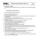
The mains has been reached the Under voltage Limit.  

Overload 

The output current has almost reached the type-specific limit 

HYST 

The set limit value for the output current has been exceeded. The output 
frequency is reduced step-by-step until the output current falls below the 
limit value again (see TAB1, SUB IMOT, function S-INT =4). 

RAMP 

The set limit value for the output current has been reached. The 
acceleration ramp is stopped (see TAB1, SUB IMOT, funct. S-INT = 3).

Br_limit 

The dynamic braking power is near the programmed limit (configurable 
by TAB2, func. BrLim). This message can be signalized by the relays or 
the open collector outputs. (TAB3, funct. REL, OC1, OC2) 

MPtFault 

Motor potentiometer function: it was enabled a preset frequency with a 
motor rotation sense different of the actual. The output frequency re-
mains unchanged (TAB1 funct. JOG = MPt). (Only with Softw. D2A-
STD) 

Overtemp 

The inverter (heat sink) temperature reaches the limit value. 
(Only with Softw. D2A-STD) 

Ot_motor 

The motor temperature reaches the limit value. 
(Only with Softw. D2A-STD) 


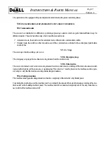
13.3.6 Operating error messages 

M

ESSAGE


D

ESCRIPTION


UNDERVOL 

Under voltage has been detected in the link. 

OVERVOLT 

The voltage in the link has reached the over voltage value. 

OVERLOAD 

The output current has exceeded the type-specific limit value. 

OVERTEMP 

The inverter (heat sink) temperature is too high. 

ILIMIT 

The set limit value for the output current has been exceeded 
(see TAB1, SUBIMOT, S-INT = 1 or 2). 

1<4Ma 

The speed reference line is interrupted or the set point is less than 4 mA.

Br_limit 

The dynamic braking power has reached its programmed limit. 

Ot_motor 

The motor temperature has been reaching the limit 
value for more than 7 seconds. (Only with Softw. D2A-STD) 

 
1.


Inverter stopped. Automatic error reset as soon as the link voltage rises above the under volt-
age value. 

2.


Inverter stopped. If the AUTORESET function is activated (see TAB3, SUB XPAR, function 
SW3), a reset is possible by setting or the 

START/STOP 

input, or the 

ENABLE 

input, or by 

setting the set point to zero. 

3.


The motor is decelerated with the deceleration ramp and the inverter is stopped. An error re-
set can be performed as described in Item 2. 

4.


The motor is decelerated with the deceleration ramp and the inverter is stopped until the tem-
perature doesn’t fall below the limit value. If the AUTORESET function is activated (see 
TAB3, SUB XPAR, function SW3), a reset is possible by setting or the 

START/STOP 

in-

put, or the 

ENABLE 

input, or by setting the set point to zero. 

5.


Behavior with Softw. D2A-STD: see 4) Behavior with Softw. D2A-1300: see 2) 


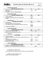
13.3.7 Hardware error messages 

An error which is established during the self-test phase or during operation is shown on the dis-
play by the message ‘‘ERROR’’ together with an error number. The inverter is stopped by the 
safety devices. 

Summary of Contents for C-530 M

Page 1: ...INSTRUCTION PARTS MANUAL Pag 1 Edition A INSTRUCTION PARTS MANUAL for Band Saw Machine type C 530 M YEAR OF PRODUCTION SERIAL NUMBER ...

Page 2: ...INSTRUCTION PARTS MANUAL Pag 2 Edition A ...

Page 3: ...e been designed and manufactured to guarantee best possible performances To keep this high standard we kindly invite you to use only original DoAll spare parts DoAll band saw machines are CE marked and in the following pages the reader will find a CE declaration which follows the European Directive 89 392 requirements DoAll is sure to assure with this machine the state of the art solutions for the...

Page 4: ...ee 14 5 2 Operator 14 5 3 Regulation 14 5 4 Typical use 14 5 5 Limits using the saw 15 5 6 Workable materials 15 5 7 Work area 15 5 8 Work place 15 5 9 Command modes stop emergency stop and out of service 16 5 9 1 Command modes 16 5 9 1 1 Stop 16 5 9 1 2 Emergency stop 16 5 9 1 3 Out of service 16 5 9 1 4 Safety precautions 16 6 TECHNICAL DESCRIPTION 17 6 1 Machine structure 17 6 1 1 Base frame 17...

Page 5: ...s 22 11 4 Safety features set up 22 12 USE OF THE MACHINE 23 12 1 Operate the machine 23 12 1 1 Control panel 23 12 1 2 To start the machine 24 12 2 Head feeding control 24 13 CALIBRATION AND TUNE UP 25 13 1 Calibration 25 13 2 Machine tuning up 25 13 3 Blade motor inverter 25 13 3 1 Control panel 25 13 3 2 Display 26 13 3 3 Help function and language selection 26 13 3 4 Inverter status 26 13 3 5 ...

Page 6: ... 15 4 Hydraulic power unit 32 15 5 Electric control panel 32 16 MAINTENANCE 33 16 1 Lubrication 33 16 2 Problems 34 16 3 Blade replacement 34 17 REMAINING DANGERS 35 18 PERSONNEL TRAINING 35 19 MACHINE DISMANTLE 35 EXHIBIT A PROOF OF TEST 36 ...

Page 7: ...to in this declaration is in compliance with CEI EN 60204 1 UNI EN 12100 1 UNI EN 12100 2 and 1 EEC Machine Directive 89 332 dated June 14 1989 and amendments 1 EEC Low Voltage Directive 73 23 and amendments 1 EEC Directive 89 336 and amendments This product uses only tested and certified components which meet the CE requirements unless otherwise specified ...

Page 8: ...cethepossibil ityofmovementtotheoperatororevengeneraterisksofinjury 1 Bealwayscautioususingthemachine because evenifitisprotectedineverydangerousspot itcanbeadanger ous equipment andthusithastobeusebeingparticularlycareful andaware 1 Giveimmediatelynoticetoyoursupervisorifthemachineneedstobemaintainedorserviced eveniftheproblem iscausedbyinexperience Anincorrectuseofthemachinecanbedangerousandcanc...

Page 9: ...d to instruct the operator to use the ma chine 1 2 REGULATIONSTOREFER This manual was written to comply to the European Machine Directive UNI EN 89 392 and following modifications andbasedon UNI EN292 1e292 2concerningasafeuseofthemachine 1 3 MANUALDESCRIPTION Thisdocumentcontainsinformationneededto 9 installandmakethemachinework 9 normaluseofthesaw 9 howtomaintainthemachine 9 howtoservicethemachi...

Page 10: ...Areaaroundthemachine 1 5meters Workingplace Machinecontrolpanel Typeoftool Bandsawblade TAB 2 2 TechnicalCharacteristics Description C 530M Roundcuttingcapacity mm 530 Squarecuttingcapacity mm 530x600 Banddrivemotor kW 7 5 Bladedimension mm 6 700x54x1 6 Bladespeed m 1 20 100 Hydraulicpumpmotor kW 2 2 Coolantpumpmotor kW 0 3 Hydraulicpumpcapacity l 1 14 Voltageofmotors Vac 400 Controlcircuitvoltage...

Page 11: ...enbandcleaningbrush Hydraulicbandtension Recirculating coolantsystem pump400 50 3 appliedthroughnozzle Bandwheeldoorinterlocks Bladeguards C26grayironcastings Thesawisbuilttowork insemi automatic 2 2 BLADESPEED The blade speed is controlled by an AC motor and a variable frequency drive which allow to regulate the blade speed withinarangeof 0 100m 1 Inthiswaythemachinecancutbothhardsteelsandaluminu...

Page 12: ...ferentthantheoneoftheoriginal manual andtoavoidthatapartialdocumentationreplacestheoriginalone 3 2 MANUALUPDATE Themanufacturerdoesnothavetoupdatethismanualifimprovementsareadoptedonnewermachinesofthesamekind oftheonethismanualmakereferenceto Thismanualwillbeupdatedbythemanufactureronlyif thismanualcontainsmistakes errors orsomethingismissing theoriginalmachineismodifiedbythemanufacturer Marginale...

Page 13: ... he sheshouldnotifythemanufacturerthatthemachinechangedownership so toallowthemanufacturertoinformthenewuseronthedangersandlimitsofliability 3 5 SUGGESTIONS Thecustomershouldnotify themanufacturerifimprovementsarenecessaryandwheretheyaretoincreaseaneasyun derstandingofthismanual ...

Page 14: ...ythemanufacturer useofnon originalspareparts otherthantheonesuggestedbythemanufacturer Partialorcompletenon observanceoftheinstructions machineusedbyuninstructedoperatorswithoutcontrolofanexpertoperator movementormachiningofnon typicalmaterials oroversizeandoverweightmaterialscomparedtotheonesindicated naturalcalamities includingearthquakes floodsorotherswhichcouldprovokedangerorfaultstothemachine...

Page 15: ...tbeusedbypeoplewithhandicapsordisables 5 3 REGULATION Designingandbuildingthismachinewerespectedthefollowinglawsandrules 9 UNIrules 9 CEIrules andmoreindetail concerningthesafetyfeatures typeAandBrules 9 EuropeanCommunityMachinedirective89 392 9 CEI EN60204 1andrelatedrulesconcerningelectrics withrespectofECdirective73 23 9 EN292 1 9 EN292 2 Ifnotclearlyspecified everycomponentusedonthismachinewas...

Page 16: ...lmachining underhumancontrol but theoperatorpresenceisnotrequiredcontinuously Itisrecommendedtokeepcleanandfreeofinterferencetheareaclosetothemachine Thismachineuseamixtureof oilandwaterascoolantliquid Thus theworkingareacouldbeslipperyanddirty THISAREAMUSTBEMARKEDBYANAPPROPRIATESIGNAL 5 8 WORKPLACE Themachinehasoneworkplaceinfrontofthecontrolpanel Asecondtemporaryworkplaceisasidethevises theregis...

Page 17: ...stopswhenthecuttingcycleisover 5 9 1 2 Emergencystop Theemergencystopstops themachineremovingtensionfromthecontrolcircuit 5 9 1 3 Outofservice Thesawcanbeturnedoutofserviceremovingtensionfromthecontrolcircuit switchingoffthemaindisconnectswitch locatedonthefrontfaceoftheenclosure Asignalsaying Outofservice mustbeplacedonthemachine anditisopera tor sdutytoverifythatthemachinecannotgeneratedangersit...

Page 18: ...uliccylinders 6 2 CUTTINGBRIDGE Pos Tab6 2Cuttingbridge 6 2 1 Cuttingbridgeframe 6 2 2 Guidingcolumns 6 2 3 Columnsconnection 6 2 4 Liftingcylinder 6 2 5 Bladetensionassembly 6 2 6 Bladedriveassembly 6 2 7 Bandbrushassembly 6 2 8 Leftandrightbandguide 6 2 9 Cuttingservo control 6 2 10 Wheels 6 2 11 Blanddrivemotor 6 2 1Cuttingbridgeframe ThecuttingbridgeframeisasteelFe37weldment itismachinedtobeas...

Page 19: ...assembly Abandbrushispoweredbyanhydraulicmotor anditcleanstheteethremovingthechips 6 2 8Leftandright bandguides Thebandguideshavetostraightenthebladecomingoutthewheel andkeepitverticalhelpingthebladeinsertionbetween theinserts Leftguidearm Moveshorizontallyonguidesmachinedonthebridge anditismovedbythemovementofthevise Rightguidearm Fixedonthecuttingbridge Itsupportsthecuttingservocontrol Boththegu...

Page 20: ...erssuctionfilter 9 a 60micron45litersoutflowfilter Thesetwofiltershavetoberemovedwhenchangingtheoilforthefirsttime after500workinghours washedusingtri chloroethaneanddriedblowingair 6 3 3Solenoidvalves Thesolenoidvalvesaremountedonblocks andthecontrolthehydraulicmovements 6 4 ELECTRICAL SYSTEM 6 4 1Controlconsole Thecontrolconsoleisontheupperpartofthecontrolenclosure 6 4 2Controlenclosure Itismade...

Page 21: ...nt 9 Theliftingequipmentmustbeenoughbigtoliftthemachine Alwaysuseonlyoneliftingequipmenttoliftthema chine nevercombinemorethenone 9 Donotusealiftforkifthelengthandwidthoftheforksareinadequatetoliftthemachine 9 If using a crank use metallic ropes and be sure they can support the weight of the machine Put strong cartoon or woodbetweentheropesandthemachine Neverleavetheropesslidefreelyonthemachinebod...

Page 22: ...itchisinsulated 9 checkifthecontrolpanelisinsulated 9 checkifthefusesandcircuitbreakersareoperative 9 checkthe3phaseelectricsource 9 ifthemachinedoesnotworkproperly donottrytofixit butimmediatelydisconnectthepowerandaskforamain tenanceexpert 9 checkthecorrectelectricalconnection 9 checkif thenecessaryprotectiondevicesworkproperly 9 checkifpushbuttonsandselectswitchworkproperly 9 checkthemechanical...

Page 23: ...danger situations Informationaboutemergenciesanddangeroussituationconcerningmachinenormaloperationsareshown AredlightintheelectricalcabinetindicatesthatelectricsareswitchedON 11 1 6 Protection devices Thebladeisprotected whereuncovered bytwoguidesthatreducetherisk butthatcannotcompletelycoverit 11 2 FIXPROTECTIONS Themovablepartsofthemachineareprotectedbyfixcovers whichcanberemovedusingtools 11 3 ...

Page 24: ... selector switches 12 1 1 Control panel The control panel looks like the following drawing 1 Blade speed readout 2 Blade speed adjusting knob 3 Blade START STOP 4 Coolant ON OFF 5 Hydraulic power unit 6 Blade replacement selector 7 Cutting cycle when pressed the vice closes the blade starts and the head start moving down 8 Vice open close 9 Cutting head up down 10 Reset 11 Emergency pushbutton E1 ...

Page 25: ...t door of the elec trical cabinet on position 0 12 1 3 When an emergency occur The emergency situation must be restored i e Covers open alarm on close the covers Then press reset pushbutton 10 and start the hydraulics again pushbutton 5 12 2 HEAD FEEDING CONTROL Head feeding is controlled by a servo controlled valve located on the side of the control panel LOADING THE MATERIAL ONTO THE MACHINE Mov...

Page 26: ...TAB3 TAB1 Programming of the basic parameters of the inverter and call up of works settings TAB2 Configuration of the analog and digi tal inputs programming of the output voltage and of the SECURITY func tion TAB3 Configuration of the analog and digi tal outputs the extended setting func tions and call up of the diagnosis function BUTTONS DESCRIPTION Function interrogation forward Function interro...

Page 27: ...NC in TAB1 funct 1 enters the language select mode Select the language by pressing the corresponding key Italian SELECT German INC English DEC The selected language will be saved automatically Press any key to return to TAB1 funct 1 13 3 4 Inverter status MESSAGE DESCRIPTION OFF No ENABLE terminals 10 11 open STOP If the AUTOSTART function is deactivated the inverter is stopped af ter switching on...

Page 28: ... specific limit value OVERTEMP The inverter heat sink temperature is too high ILIMIT The set limit value for the output current has been exceeded see TAB1 SUBIMOT S INT 1 or 2 1 4Ma The speed reference line is interrupted or the set point is less than 4 mA Br_limit The dynamic braking power has reached its programmed limit Ot_motor The motor temperature has been reaching the limit value for more t...

Page 29: ...send the unit to the after sales service for inspection ERROR CAUSE REMEDY ERROR 1 Data error Reprogram parameters ERROR 2 Hard and software is not compatible ERROR 3 CPU error ERROR 4 Keypad error ERROR 5 Error in ROM ERROR 6 Watchdog error ERROR 7 Clock error ERROR 8 Program error ERROR 9 Output stage error Have unit checked by technical after sales service ...

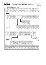
Page 30: ...INSTRUCTION PARTS MANUAL Pag 30 Edition A 13 3 8 Programming structure ...

Page 31: ...INSTRUCTION PARTS MANUAL Pag 31 Edition A ...

Page 32: ...machinedangers andavoid ingunnecessaryrisks WHEN SERVICING THE SAW ALWAYS DISCONNECT THE ELECTRIC SOURCE THE OPERATOR MUSTUSETHEENTIRESAFETYEQUIPMENT GLOVES GLASSESANDBOOTS Theusermustwearallthenecessaryprotectiondevices gloves glassesandshoes THE MANUFACTURER CAN NOT BE JUDGED LIABLE FOR INJURIES OR DAMAGES DUE TO UNATTENDED SAFETY RULES BY THE USER 15 1 BASE 15 1 1 Base Basedwg 210 01 001 Pos To...

Page 33: ...17 003 15 2 7Bandbrushassembly Bandbrushassemblydwg 210 20 Pos Tool Checkandifnecessaryreplacethebandbrush 20 014 Spanner Registerthebrushsotokeepthebladeteethalwaysclean 15 2 8Wheels Wheel 03 042 0 Pos Tool Checkthewheeladjustment Checkthebladepositiononthewheel Ifthebladebacktouchesthewheel callthemanu facturer 03 042 Manufacturer Checkandkeepcleanthewheelgrooves 03 042 Besurethebladeisnotcuttin...

Page 34: ...first100hours Checkthelevelevery2000hours Replaceevery4000hours Columns DLoadingplug ELevel AGIPEXIDIA68 BPENERGOLHP60 C TOTALCARTEREP68 Checkweekly Wheel FBearings AGIPGRMU2 BPMACH GREASELT2 TOTALMULTISMS Checkweekly Hydraulicpowerunit GLoadingplug HUnloadingplug AGIPOSO46 FINAHYDRAN46 BPENERGOLHLP46 ESSONUTOH46 TOTALAZOLLA46 Replaceoilafterfirst500hours Checkthelevelevery500hours Replaceevery200...

Page 35: ...uideguidestheblade Regulatetheguides Bladestalls Feedrate Reducethefeedrate Themotorsareoff Problemswiththeelectricsource Wrongcircuitbreakers Shortcircuit Lookfortheproblemandsolveit 16 3 BLADE REPLACEMENT 1 Raisecompletelythesawhead 2 Wearprotectiongloves 3 Rotate the band tension wheel CW so to release tension or work on the band tension handle for machines equippedwithhydraulicbandtension 4 St...

Page 36: ...rcerespectingtheCEI64 8orothercountriesspecialruleswhere themachinewasinstalled 18 PERSONNELTRAINING Thismachinewasdesigntobeeasilyoperated Itisnotexpresslyrequiredanexperttooperatethesaw butanexpertcan setasbestaspossiblethemachinesotoobtainthemaximumresults Therefore theoperatorneedsagoodexperienceinmachinetools especiallyinbandsawmachine Theinternalmaintenancepersonnelshouldbeabletoreadandunder...

Page 37: ...MBER C 530M M Has been tested in accordance with the following norms UNI EN 292 1 UNI EN 292 2 CEI 60204 1 CEI 44 5 The test had positive result as per testing sheet Hours of hydraulic power unit for testing purpose Numbers of cuts done for test purpose Electrical test Hydraulic test Mechanic test Check Signed ...

Reviews: