DMP Electronics CellCom LTE Series Programming And Installation Manual Download Page 27

CellCom‑LTE Programming and Installation Guide 

Digital


Monitoring


Products

23

TIME CHANGES

Choose 

YES

 to allow the communicator to request automatic time changes from the 

SCS‑1R or SCS‑VR receiver. The receiver must be programmed to send and receive time 

change updates from the host computer at least every 24 hours. Choose 

NO

 to disable 

automatic time change requests. The default is 

YES

.

HOURS FROM GMT

When time zone is programmed 

YES

, enter the number (0‑23) that indicates the 

Greenwich Mean Time zone (GMT) where the communicator is located. The default is 

6

See Table 6 for GMT values.

GMT CITY/TIME ZONE

GMT CITY/TIME ZONE

0

London, Monrovia, Lisbon

12

Fiji, Marshall Island, Wellington

1

Cape Verde Island, Azores

13

New Cadelonia

2

Mid‑Atlantic

14

Guam, Sydney

3

Buenos Aires, Georgetown

15

Tokyo, Seoul

4

Atlantic Time (Canada), Caracas

16

Hong Kong, Singapore

5

Eastern Time (US, Canada) Bogota

17

Bangkok, Hanoi

6

Central Time (US, Canada) Saskatchewan 18

Dhaka, Almaty

7

Mountain Time (US, Canada), Edmonton

19

Islamabad, Karachi

8

Pacific Time (US, Canada), Tijuana

20

Abu Dhabi, Kazan

9

Alaska

21

Moscow, Bagdad

10

Hawaii

22

Eastern Europe

11

Midway Island, Samoa

23

Rome, Paris, Berlin

KEYPAD INPUT

Select 

NONE

 to allow zone 4 to function as normally programmed. The default is 

NONE

Select 

ECP

 to enable communication between the communicator and an Ademco/

Honeywell panel using the +Z4‑ terminals. Using the Ademco/Honeywell ECP Bus, the 

communicator can add, delete, and change user codes as well as arm and disarm the 

Ademco/Honeywell panel. The communicator will forward alarm messages from the 

Ademco/Honeywell panel to the central station.
Select 

DSC

 to enable communication between the communicator and a DSC PowerSeries 

panel using the Z4‑ terminal. Using the DSC bus, the communicator can add, delete, 

and change user codes as well as arm and disarm the DSC panel. The communicator will 

forward alarm messages from the DSC panel to the central station.
See Ademco/Honeywell ECP Connection for examples of panel wiring and necessary 

Ademco/Honeywell panel programming.
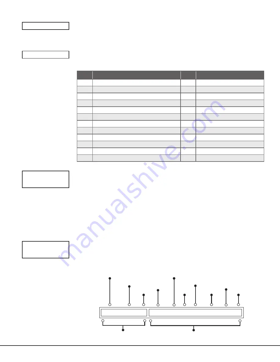
CID FORMAT

Select 

DMP

 to send CID messages as Serial 3 format. Select 

CID

 to send messages as DMP 

string with raw CID message appended. Refer to Figure 16. Default is 

DMP

.

This feature requires SCS‑VR Version 1.4.6 and higher or SCS‑150 Version 107 and higher. 

TIME CHG  NO 

YES

HRS FROM GMT: 

6

Table 6: GMT Time Zones 

KYPD INPUT

NONE    

ECP    DSC

CID FORMAT

DMP    

CID    

9910   3155   c   5550   18   1   110   00   010   2

The receiver sending 

the message

The account number 

of the DMP panel

CID Identifier

The account number 

of the host panel

The message type 

that identifies 

the message as CID

The new event

The event code

for a Zone Fire Alarm

Partition

Number

Zone

Number

Checksum

DMP String

CID String

Figure 16: CID Format Option

Summary of Contents for CellCom LTE Series

Page 1: ...CellCom LTE V Series Communicator Digital Monitoring Products Inc 2020 PROGRAMMING AND INSTALLATION GUIDE...

Page 2: ...n 14 Programming 15 Before You Begin 15 Getting Started 15 Programming Menu 15 Reset Timeout 16 Special Keys 16 Letters and Special Characters 17 Current Programming 17 Initialization 18 Clear All Cod...

Page 3: ...Message To Transmit 27 Output Number 27 Output Action 28 Swinger Bypass 28 Cross Zone 28 Receiver Routing 28 Zone Number 28 Stop 29 Set Lockout Code 29 Stop 29 Set Lockout Code 29 Appendix 30 ECP Pass...

Page 4: ......

Page 5: ...COMPONENTS Terminals Power Connection Terminals The communicator may be powered from the 12 VDC or 24 VDC auxiliary output of the control panel Observe polarity and use 18 22 AWG wire to connect the c...

Page 6: ...tion information type to direct with a baud rate of 38400 and choose the appropriate COM port 4 Select Panel Remote Update then select the correct RU file for the communicator 5 Press and hold the loa...

Page 7: ...IVITY OPERATION Green Steady Communicator Disarmed Primary Power OK No Light No Power Red Steady Communicator Armed Primary Power OK ECP and DSC Passthru Perform an ECP or DSC Passthru and communicate...

Page 8: ...place to protect the communicator from damage due to tampering or the elements It is not necessary to remove the PCB when installing the communicator Figure 1 System Components DC Z1 Z2 Z3 G T R Z4 O1...

Page 9: ...nnect the Antenna Place the antenna onto the SMA connector Refer back to Figure 1 Twist the antenna until it is securely tightened Replace the housing cover on the mounted base Be sure to not damage a...

Page 10: ...y Use a normally closed output on a burglary control panel to indicate a burglary alarm The communicator zone should be programmed with a zone name and burglary zone type When the output on the contro...

Page 11: ...adence type zone number and type of message sent to the receiver The communicator generates zones 5 and 6 using the zone name of zone 4 to send to the central station Zones 5 and 6 cannot be preprogra...

Page 12: ...O1 O2 Use 18 22 AWG for Power Supply connection 1k Z4 DMP Panel 12 VDC Aux Output ADEMCO Panel 12 VDC Aux Output BELL 12 VDC BELL NAPCO Panel 12VDC Aux Output BELL 12 VDC BELL DSC Panel 12 24 VDC Aux...

Page 13: ...n about configuring ECP Passthru refer to COM Series How To Guide ECP Passthru LT 2209 PROG B R RESET LOAD DC Z1 Z2 Z3 G T R Z4 O1 O2 DualCom 1 2 3 4 5 6 7 8 9 10 11 12 13 14 15 16 17 18 19 20 21 22 2...

Page 14: ...on 2 0 or higher VISTA 15 Yes No No No No VISTA 15P Yes Yes Yes Yes Firmware version 5 2 or higher VISTA 20SE Rev 12 or higher No No No No VISTA 20P Yes Yes Yes Yes Firmware version 5 2 or higer VISTA...

Page 15: ...nnection Model 330 DSC PC LINK 1 CON 4 YELLOW GREEN YELLOW GREEN TAB UP Figure 9 DSC Passthru Wiring COMMUNICATOR TO DSC WIRING Communicator Terminal DSC Terminal DC RED DC BLK Z4 YEL Z4 GRN T or T1 T...

Page 16: ...tput or remote arming output in output options when programming the communicator See Armed Output or Remote Arming Output The communicator output connections can be used with any of the applications l...

Page 17: ...minal 23 on the control panel 4 Connect the R ring terminal on the communicator to terminal 24 on the control panel 5 Power the communicator by connecting its terminal 12V to terminal 5 on the control...

Page 18: ...o the panel Press Yes 13 Configure additional options as needed then press Save Tech APP Activation 1 Go to the Customer Summary Systems 2 Tap the Add icon 3 Enter the System Name 4 In System Type sel...

Page 19: ...ed or deleted in panel programming To revert the default code to 99 use the Clear All Codes option found in the Initialization menu Panels ship with the master code on the serial number label in paren...

Page 20: ...ress CMD to advance to the next step CMD is also used to enter information into the communicator s memory such as an IP address or a zone name Press CMD after entering information Back Arrow Use the b...

Page 21: ...er character or press CMD if finished NUMBER SELECT KEY 1 SELECT KEY 2 SELECT KEY 3 SELECT KEY 4 1 A B C 2 D E F 3 G H I 4 J K L 5 M N O 6 P Q R 7 S T U 8 V W X 9 Y Z space _ 0 Standard Keyboard Press...

Page 22: ...NG Choose NO to leave existing zone information intact Choose YES to set all zones in the system to UNUSED CLEAR COMMUNICATION Choose NO to leave existing communication programming intact Choose YES t...

Page 23: ...ly if this option is used FAIL TIME MINUTES Fail time allows the SCS 1R or SCS VR receivers to miss a defined number of check ins before logging that the panel is missing For example if cell check in...

Page 24: ...the receiver The default is NO Supervisory Trouble Reports Choose YES to enable Supervisory Trouble Trouble Restoral Force Armed Late to Close and Fault reports to be sent to this receiver Choose NO...

Page 25: ...remotely The default is YES Choose NO to disable remote disarming REMOTE OPTIONS RMT KEY DISARM NO YES SYSTEM REPORTS This option allows you to select which reports the communicator sends to the rece...

Page 26: ...zone time can be from 4 250 seconds in one second increments Enter 0 to disable the cross zone time feature See Cross Zoning POWER FAIL DELAY Enter the time allowed for a power failure to occur befor...

Page 27: ...to enable communication between the communicator and an Ademco Honeywell panel using the Z4 terminals Using the Ademco Honeywell ECP Bus the communicator can add delete and change user codes as well a...

Page 28: ...e can be 1 15 minutes Enter 0 to provide continuous output Note The output is cutoff within 60 seconds of the programmed cutoff time The cutoff timer is shared by all outputs If a second output trips...

Page 29: ...bad zones If a closing report is sent the user number is indicated as SCH on the SCS 1R or SCS VR receivers Choose NO to disable automatic arming for this area The default is NO Bad Zones At the time...

Page 30: ...e responses are made automatically for the zone There are 12 zone types to choose from including Blank To select a new zone type press any select area The display lists the four zone types shown below...

Page 31: ...when ZONE NO appears on the display Choose NO to make changes to the alarm action for a zone ALARM ACTION Change the default alarm characteristics of a zone type If you selected the non 24 hour zone t...

Page 32: ...he receiver if bypass reports is set to YES CROSS ZONE Choose YES to enable cross zoning for this zone Cross zoning requires this zone to trip twice or this zone and another cross zoned zone to trip w...

Page 33: ...Code You can change this code at any time to any combination of numbers from 1 5 digits long 1 65535 Do not use leading zeros for the lockout code 1 Press any select area The keypad displays ENTER COD...

Page 34: ...eports are enabled in the Ademco Honeywell panel a duplicate message will also be sent to the central station Note Communicators with Version 194 and higher do not require you to log in to the VISTA p...

Page 35: ...P SETUP and press any select key or area 2 At ECP SETUP VISTA 128 If the panel is a VISTA 128 select YES If the panel is a different model select NO 3 At INST CODE enter the ECP panel installer code a...

Page 36: ...eypad buzzes END Press this select area to stop the walk test When the walk test ends or a 20 minute timeout expires a final sensor reset occurs The system test end message is sent to the receiver alo...

Page 37: ...owing a Program output 17 to turn on when armed Stay Output Funct Enter 01 Press to continue Summary Screen 01 A E P Trig Press to continue Activated by Enter 2 Press to continue Enter Zn Type Enter 2...

Page 38: ...HI HI HI LO LO LO LO HI HI LO LO HI HI LO LO HI TIP BROWN RING GRAY TIP GREEN RING RED BLACK RED SYNC COM DATA USE SA4120XM 1 CABLE 1 2 3 4 5 6 7 8 OUT 17 12 AUX GND OUT 18 VISTA 20P ONLY Ademco Vista...

Page 39: ...gital Monitoring Products 35 Bosch Control Panel Option Bus to CellCom LTE for Reduced Noise Disturbance Option Bus CellCom LTE V PROG 12 G Z1 Z2 Z4 Z4 G Z3 R T O2 O1 R B Control Panel R B G Y Figure...

Page 40: ...ed radio TV technician for help Changes or modifications not expressly approved by the party responsible for compliance could void the user s authority to operate the equipment If necessary the instal...

Page 41: ...hite 685 R Surface Mount Conduit Backbox red 383 Replacement Dual Band Cellular Antenna 330 DSC DSC Remote Programming Harness Compatibility ECP Passthru VISTA 15 VISTA 20 VISTA 21 VISTA 128 DSC Passt...

Reviews: