background image

DMEGC Photovoltaic Modules Installation Manual

- 6 -

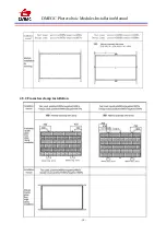
4.3 conventional requirements

The module mounting structure must be made of durable, corrosion-resistant and UV-resistant
material. Always use a tested and certified mounting structure approved for your system design.

Ensure the installation method and supporting system of modules is strong enough to withstand all the
load conditions. Always observe the instructions and safety precautions included with the module
support frames.

In regions with heavy snowfall in winter, select the height of the mounting system so that the lowest
edge of the module is not covered by snow for any length of time. In addition, ensure that the lowest
portion of the module is placed high enough so that it is not shaded by plants, trees or damaged by
ground soil moved by or through the air.

For ground mounting systems, the minimum distance DMEGC recommend from the ground to the
bottom of the module is at least 24 inches (60cm).

Modules must be securely attached to the mounting structure. For Clamping System installation
methods, the recommended maximum compression for each clamp is 2900 PSI (20 Mpa) in order to
avoid potential damages to module frames. Follow the instruction of the clamping system supplier.
Provide adequate ventilation under the modules in conformity to your local regulations.

Provide adequate ventilation under the modules in conformity to your local regulations. A minimum
distance of 10 cm between the roof plane and the frame of the module is generally recommended.

Avoid the frame receiving the lateral tension and pressure, causing the flame off or crushing the glass.

Before installing modules on a roof, always ensure the roof construction is suitable. In addition, any
roof penetration required to mount the module must be properly sealed to prevent leaks.

Observe and take into account the linear thermal expansion of the module frames (the recommended
minimum distance between two modules is 1 cm).

When installing a module on a pole, select a pole and module mounting structure that will withstand
the anticipated wind load and snow load for the area.

Ensure modules are not subjected to wind or snow loads exceeding the maximum permissible loads,
and are not subject to excessive forces due to the thermal expansion of the support structures. Never
allow modules overlap or exceeds the rooftop: Refer to the following installation methods for more
detailed information.

Summary of Contents for DM M2-60BW Series

Page 1: ...agnetics Co Ltd DMEGC Solar Energy Hengdian Industrial Area Dongyang City Zhejiang Province China Tel 86 579 86554950 Fax 86 579 86554845 Email solar dmegc com cn DMEGC Photovoltaic Modules Installati...

Page 2: ...RE SAFETY 4 3 PRODUCT IDENTIFICATION 4 4 MECHANICAL INSTALLATION 5 4 1 SELECTING THE LOCATION 5 4 2 TILT ANGLE SELECTION 5 4 3 CONVENTIONAL REQUIREMENTS 6 4 4 INSTALLATION METHODS 7 4 5 ATTACHMENT GUI...

Page 3: ...30 applocation class A Modules rated for use in this applications class may be used in system operating at greater than 50V DC or 240W where general contact access is anticlpated Modules qualified for...

Page 4: ...they are ready to be installed Store pallets in a ventilated rain proof and dry location until the Modules are ready to be unpacked During the transportation do not to apply direct pressure on the bac...

Page 5: ...module unnecessarily during installation The glass surface and the frame may be hot there is a risk of burns and electric shock Do not work in the rain snow or in windy conditions Avoid exposing cabl...

Page 6: ...heet and the mounting surface Roof construction and installation may affect the fire safety of the building Improper installation may create hazards in the event of a fire Use appropriate components s...

Page 7: ...he coastline Confirm with DMEGC install after obtaining approval Modules must be installed or operated in areas where salt hail snow sand dust air pollution chemically active acid rain soot etc are ex...

Page 8: ...is 2900 PSI 20 Mpa in order to avoid potential damages to module frames Follow the instruction of the clamping system supplier Provide adequate ventilation under the modules in conformity to your loc...

Page 9: ...e suggest stainless steel M8 bolts should be around 15 20 N m the mounting details are shown in the following figures 4 4 2 Mounting with Clamps When choosing this type of clamp mounting method use at...

Page 10: ...eet a maximum positive pressure of 1600Pa and negative pressure of 1600 Pa this design load was then tested with a safety factor of 1 5 times The high loading capacity applies to severe environment li...

Page 11: ...DMEGC Photovoltaic Modules Installation Manual 9 4 5 1Framed module bolt and clamp installation...

Page 12: ...DMEGC Photovoltaic Modules Installation Manual 10 4 5 2 Frameless clamp installation...

Page 13: ...mum number of series connected modules depends on system design the type of inverter used and environmental conditions Based on the maximum series fuse rating of module and local electrical installati...

Page 14: ...l utility are generally required Especially for larger installations DMEGC recommends lightning protection following the local requirements and regulations 6 Grounding For grounding and bonding requir...

Page 15: ...381 are used with metal framed photovoltaic solar panels and related products that require grounding for safety reasons 3 Addition Third party Grounding Devices DMEGC PV Modules can be grounded using...

Page 16: ...ater and a soft sponge or cloth for cleaning A mild nonabrasive cleaning agent can be used to remove stubborn dirt In order to reduce the potential for electrical and thermal shock DMEGC recommends cl...

Page 17: ...out of or in any way connected with such installation operation use or maintenance No responsibility is assumed by DMEGC for any infringement of patents or other rights of third parties which may res...

Page 18: ...xxxB6 60NT DMGxxxB6 60NT DMxxxM2 B60NT DMxxxM2 B60NT Group 5 72 156 75 cells modules with aluminium frame xxx 355 370 in increment of 5 DMGxxxM6 72BT DMGxxxM6 72BW DMGxxxM6 72ST DMGxxxM6 72SW DMGxxxM6...

Page 19: ...DMxxxM2 B72HBT DMxxxM2 B72HSW DMxxxM2 B72HBW Group 11 120 166 cells modules with aluminium frame xxx 355 375 in increment of 5 DMxxxM6 G60HST DMGxxxM6 G60HBT DMxxxM6 G60HSW DMxxxM6 G60HBW Group 12 120...

Reviews: