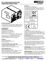


MPT-250B SPECIFICATIONS AND
OPERATING INSTRUCTIONS
DATASHEET
______________________________________________________________________
Daniels Manufacturing Corporation, 526 Thorpe Road, Orlando, FL 32824, U.S.A.
Phone: (407) 855-6161 • Fax (407) 855-6884 •
• Email:
Copyright©2013 All Rights Reserved Page 2 of 6
Rev. M 10/13 MPT-250B-DS
2. SETUP
The Alphatron MPT-250B is shipped from the factory pre-calibrated and tested. To assure consistent, correct results, users
should familiarize themselves with the setup and operation of the unit before placing it in service.
To operate, set the MPT-250B on a flat, level surface in an upright position. The unit can be tilted with the adjustable front feet
to ease operator viewing of the display. Do not handle, pick up or move the unit by exerting leverage against any front or rear
panel controls, fixtures or connections. Always lift by the base plate, preferably at the mid-point along either side. DO NOT use
the lower grip as a handle for lifting or moving the MPT-250B. This can result in permanent damage to the load cell sensing
unit.
3. ASSEMBLY
3.1 UPPER GRIP
The MPT-250B is shipped with the upper grip installed.
3.2 LOWER GRIP
The MPT-250B is shipped with the standard lower grip installed. If an optional lower grip was ordered it will be
necessary for the purchaser to install it.
3.2.1
Self-tightening cam type lower grip (optional)
To install the self tightening cam type lower grip proceed as follows:
A.
Remove the screw holding the standard lower grip in place.
B.
Place the screw in the mounting hole of the self-tightening cam type lower grip. To get the screw head past
the operating gears into its recess, use the operating lever to rotate the cams into the fully open position.
C.
Screw the assembly firmly into place in the load cell sensing unit.