DLS CC-2 User Manual Download Page 10

10

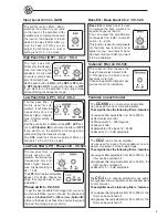
If problems occour during the installation, or later, 
this guide might help you to find out whats´s wrong.

THE AMPLIFIER IS DEAD:
1.

 Check power lead, ground and remote connec 

    tions at the amplifier using a multi meter. 

2.

 Check the battery terminal connections.

3.

 Check the power lead fuse or circuit breaker. If 

    fuse damage continues, inspect the power lead 
     for short circuits. 

4.

 Check the amplifier protection fuses. Are these 

    broken change to new ones with the same value.  
     If short circuiting continues, contact your local 
     DLS dealer. A fault may exist in the amplifier. 

5.

 To start the amplifier requires a remote voltage of 

    9-15 volt. Check the voltage with a multi meter. 

AMPLIFIER PROTECTION FUSE BLOWS AT LOW 
VOLUME : 

1.

 One or more speaker cables are shorted. Make an 

insulation test with a multi meter. The cables must not 

have a connection to earth. 

THE AMPLIFIER TURNS OFF AFTER 10 - 30 MI-
NUTES. 

The amplifier is overheating due to inadequate ventila-

tion. Check mounting position is free from obstruction. 

Do this:

1.

 Move the amplifier to a place with better ventil-

    ation.

2.

 Install one or two fans to cool down the heat- 

    sink. 

3.

 Overheating can also be caused by an  


    impedance load below the level permitted. 

NO OUTPUT FROM ONE OR MORE SPEAKERS:

Check the following:

1.

 Balance control position.

2.

 Fader control position.

3.

 Speaker cable connections to both ampli   

    fier and drivers.

4.

 Signal lead plugs and cables.

5.

 Change left and right signal lead plugs in the 


 amplifier to see if the problem moves to a diffe-

    rent speaker, the lead has a fault. 

    If the problem remains, the speaker or amplifier  

    are at fault.

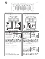
Troubleshooting Testing 

Before you finish the installation, you should do the 
following tests to make sure the wiring is correct and 
everything is operating properly.

Reconnect Battery

When wiring is complete, 
reconnect the battery 
negative terminal.

Test speaker connections

Make sure the speakers are connected right. Use 
the balance control on the head unit to make sure 
right channel is on right speaker etc. If speakers 
don´t play at all, one or both speaker wires may 
be disconnected.

Test power wiring

 1. Turn on the head unit but do not turn up the  
      volume. The amplifier power light should come  
     on. If not, check the remote and +12 volt wires.  
     Also check the ground connection.
 2. Turn up the head units volume slightly. All spea- 
     kers should operate. if not, check wiring    
     connections at amplifier and speakers.

Summary of Contents for CC-2

Page 1: ...C 2 speaker wiring Front speakers 7 Subwoofer 7 CC 4 speaker wiring Four speakers 8 Two speakers and bridged subwoofer 8 Two subwoofers or a stereo speaker pair connected in bridge mode 9 Testing 10 Troubleshooting 10 Professional tips 11 Specifications 12 Technical Assistance For technical assistance ask the shop where the product was sold or the distributor in your very country Information can a...

Page 2: ...4 accept AWG 5 cables so If possible buy AWG 5 16 mm2 cable for best performance CC 500 accepts AWG 2 33 mm2 power cable Both the positive wire and the ground wire must have the same size NOTE To avoid cable fire be sure not to oversize the main fuse value for the power wires THE DC FEED Maximum main fuse values for different cable sizes 6 mm2 9 AWG 25 A 10 mm2 7AWG 40 A 16 mm2 5AWG 60 A 21 mm2 4A...

Page 3: ...igh level input cable if high level input is used Wire ties Insulating grommet or insulating tube Power wiring Use only ATC blade type fuses of the same value when repla cing a blown fuse CC 500 has no internal fuse so we recommend the use of an external fuse Fuses Power terminal 12V Be sure to use a rubber grommet or a plastic insu lating tube where the cable passes the firewall or other places w...

Page 4: ... the best sound quality 4 For RCA cable signal input Connect the radio power antenna lead remote turn on off from the car stereo to the amplifier remote connection This turns on the amplifier whenever the car stereo is turned on You can either use the built in remote cable in the RCA cable itself or use a separate cable Sometimes a small disturbance may enter the amp lifier coming from the remote ...

Page 5: ... and the HPF LPF but ton to LPF button IN to activate the filter or OFF if you want to run the amplifier in full range mode without limiting the frequency range The CC4 model has the same setup of filters on channels 1 2 and 3 4 as well Low Pass filter LPF CC 2 CC 4 Features on each model Bass EQ Bass boost CC 2 CC 500 Bass EQ or Bass boost is used to increase the bass volume at a specific frequen...

Page 6: ... level control box The external remote works together with the interanal gain control the set ting of the internal gain decides the maximum level also for the external level control Connect to REMOTE socket on CC 500 Remote sub level control The low pass filter is mostly used for sub woofers It will allow low frequencies only and blocks higher frequen cies A typical setting is 60 70 Hz The LPF fil...

Page 7: ...CH 1 2 for 2 channel stereo use Filter settings CH 1 2 for subwoofer use The high pass filter blocks very low fre quencies from reach ing the speakers mostly used to protect small speakers from deep bass Set the push button to ON and the HPF LPF button to HPF button OUT to activate the filter or OFF if you want to run the amplifier in full range mode without limiting the frequency range Adjust wit...

Page 8: ... low frequen cies only and blocks hig her frequencies Atypical setting is 60 70 Hz Set the push button to ON and the HPF LPF button to LPF button IN to activate the filter The high pass filter blocks very low fre quencies from reach ing the speakers mostly used to protect small speakers from deep bass Set the push button to ON and the HPF LPF button to HPF button OUT to activate the filter or OFF ...

Page 9: ...s filter is mostly used for sub woofers It will allow low frequencies only and blocks higher frequen cies A typical setting is 60 70 Hz Set the push button to ON and the HPF LPF button to LPF button IN to activate the filter When the CC 4 is used for bridging a stereo speaker pair set use only the HPF filter Set the push button to ON and the HPF LPF button to HPF button OUT to activate the filter ...

Page 10: ...ol down the heat sink 3 Overheating can also be caused by an impedance load below the level permitted NO OUTPUT FROM ONE OR MORE SPEAKERS Check the following 1 Balance control position 2 Fader control position 3 Speaker cable connections to both ampli fier and drivers 4 Signal lead plugs and cables 5 Change left and right signal lead plugs in the amplifier to see if the problem moves to a diffe re...

Page 11: ...ght battery Tap the wire on to the terminal of the battery and observe the movement of the cone The cone should move outwards when the wire touches the battery and inwards when the battery is removed If it is the other way around the speaker has been connected backwards and it must be removed and connected correctly If your system also has a subwoofer connected through a passive 6 or 12 dB crossov...

Page 12: ...sumption max 43A 40A Fuse 2 x 20 A Internal fuse 40 A under bottom plate Dimensions HxWxD mm 51 x 129 x 260 51 x 129 x 250 Dimensions inch 2 x 5 07 x 10 2 2 x 5 07 x 9 85 Weight 1 87 kg 1 8 kg All output power ratings are RMS Watts 14 4 VDC CEA standard CC 500 Number of channels 1 Amplifier class D Power output RMS 1 ohm 800 W Power output RMS 2 ohm 600 W Power output RMS 4 ohm 350 W Signal to noi...

Reviews: