background image

MSD600M - Technical Reference Manual

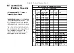
15.5 Appendix D-5. Factory
Preset 4: LRCS Pro-Logic
Surround Sound

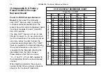
Preset 4 LRCS Pro-Logic Surround
Sound

. In this preset the DK-Audio 

Jelly-Fish™ figure is used to monitor a 
4-channel surround sound signal. The
preset shows four discrete analogue inputs
from input modules I1 and I2 (lines #33,
#34, #37 and #38).
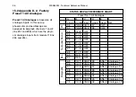
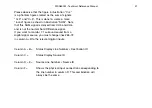
The Jelly-Fish™ figure is set up via lines
#55–62 in column A + B. As can be seen
from the illustrations, this particular set up
uses five vectors in order to show the
surround sound information. The ”CENT”
figure is coupled to the bargraph showing
the centre information, and vector ”C + 1”
is coupled to the bargraph showing the
information from the right channel.
Please observe that the two vectors 
”C + 2” and ”C + 3” are both coupled to
the information from the surround sound
channel.
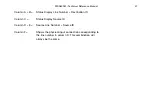
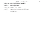
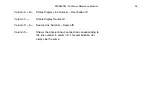
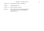
When feeding a signal to the surround
sound channel (S) you will get a figure as
shown in the ”surround” illustration.

44

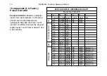
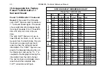
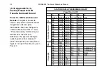
STATUS DISPLAY REFERENCE CHART

Preset No. 4 LRCS

A

B

C

D

E

F

Line # Output Input

Line # Input

Ref.

53

PHAS

CH 1

57

CH 1

54

PHAS

CH 2

58

CH 2

55

CENT

CH 3

59

CH 3

56

C + 1

CH 2

58

CH 2

57

C + 2

CH 4

60

CH 4

58

C + 3

CH 4

60

CH 4

59

C + 4

CH 1

57

CH 1

60

C + 5

OFF

61

C + 6

OFF

62

C + 7

OFF

63

RES

OFF

64

RES

OFF

65

CH 1

L

33

L

Analogue 1 L

66

CH 2

R

34

R

Analogue 1 R

67

CH 3

C

37

C

Analogue 2 L

68

CH 4

S

38

S

Analogue 2 R

69

CH 5

OFF

70

CH 6

OFF

71

CH 7

OFF

72

CH 8

OFF

Bar

graphs

Res.

Surr

ound Sound       PH

Summary of Contents for MSD600M

Page 1: ...s Manual www dk audio com MSD600M Technical Reference Manual MASTER STEREO DISPLAY interstage Phistersvej 31 2900 Hellerup Danmark Telefon 3946 0000 fax 3946 0040 www interstage dk pro audio with a s...

Page 2: ...without prior written consent from DK Audio A S Denmark Trademarks Analog Devices is a registered trademark of Analog Devices Inc USA Crystal is a registered trademark of Cirrus Logic Inc USA AKM is a...

Page 3: ...nterface 9 4 7 DSP Microcomputer 10 4 8 Flash PROM 10 4 9 LCD Display 11 4 10 Power Supply 11 5 Modules 12 5 1 Module Configuration 15 5 2 Mixing Modules 15 6 Mounting 16 7 Audio Connections Breakout...

Page 4: ...5 1 Appendix D 1 Factory Preset 0 Base Setup 36 15 2 Appendix D 2 Factory Preset 1 All Analogue 38 15 3 Appendix D 3 Factory Preset 2 All AES 40 15 4 Appendix D 4 Factory Preset 3 LR 42 15 5 Appendix...

Page 5: ...Registration Card to send us your remarks and observations Your Registration Card is also the easiest way for you to receive up to date informa tion from DK Audio on future Master Stereo Display prod...

Page 6: ...atrix The MSD600M features a full 32 x 16 Audio Matrix which allows up to 8 analogue or 32 digital input channels mono to be routed to any of max 8 analogue digital output channels and or to their ass...

Page 7: ...MSD600M Technical Reference Manual 3...

Page 8: ...his can be done by applying the same input signal or a signal synchronised to the input signal to the external Sync Input 3 The External Sync is mainly used in two situations 1 The user will synchroni...

Page 9: ...MSD600M Technical Reference Manual 5 See notes opposite page...

Page 10: ...e the external sync auto detect feature Once a valid sync signal is present the MSD600M will always select this for its system sample rate clock Even though the AES 3 External Sync Input will lock up...

Page 11: ...MSD600M Technical Reference Manual 7...

Page 12: ...Input signal there are three types of input modules to select from see next section in this manual Common for all is that they are designed around the Cirrus Logic AES 3 receiver chip the CS8420 This...

Page 13: ...The AES 3 outputs will always be syn chronous to the used master clock which either can be driven from the external sync input or from an internal 48 kHz clock oscillator Combined with the SRC on the...

Page 14: ...d The Software Version referred to in the Info Menu is the Software running on this DSP Microcomputer The used DSP is the Analogue Devices ADSP 2181 a single chip microcomputer optimised for digital s...

Page 15: ...com monly used LCD displays but so much better Remember You See What You Hear 4 10 Power Supply The MSD600M is using an external power supply of the desktop type This enables the MSD itself to be more...

Page 16: ...modules can be installed very easily accommodating up to 32 digital AES 3 and or 8 analogue inputs mono simultaneous with up to 8 analogue 8 digital AES 3 outputs mono One of the output slots can alte...

Page 17: ...MSD600M Technical Reference Manual 13...

Page 18: ...1 Stereo transformer balanced Analogue Input 1 Digital AES Input 24 bit MSD600M Input 2D O 2 Digital AES Inputs 24 bit MSD600M Input 4D O 4 Digital AES Inputs 16 bit MSD600M Input SDI SDI de embedder...

Page 19: ...cognises the input configuration and automatically lists them in the Audio Matrix Menu ready to use 5 2 Mixing Modules When mixing input modules of different types there are some guidelines for which...

Page 20: ...h horizontally and vertically for the best viewing angle Screw the base plate to your console or work surface using two 4mm wood screws or an appropriate alternative depending upon the materi al Place...

Page 21: ...breakout cables have all the necessary DSUB connectors to XLR audio in out connectors Diagrams for all available breakout cables are avail able on our web site www dk audio com Detailed information r...

Page 22: ...arizer is very soft and easily scratched only use a soft dry cloth without chemicals for cleaning Do not allow water or liquids to remain on the surface for long This may cause local deformation or di...

Page 23: ...MSD600M Technical Reference Manual 19...

Page 24: ...nual on how to re assign input sources and outputs destinations in the Matrix 20 Preset Preset Name Description Modules MSD600M Source Ana Dig 0 Base Setup This is the default power up 4 Ana Dig setti...

Page 25: ...and will show these even if the corresponding input module is not mounted Please note that all presets assumes that the MSD600M is fitted with the Analogue Digital Input module MSD600M Input 1 Even pr...

Page 26: ...22 MSD600M Technical Reference Manual 10 The DK SCALE PC Software Program...

Page 27: ...ive the user the freedom of choosing specific scales from the library it also gives the opportunity to design your own scale The DK Scale program is a DOS program but can be run from inside a DOS box...

Page 28: ...2 If a COM port has not been set the update program will abort The command SET MSD LOAD is valid only for the actual DOS box This means that the update program must be executed from the same DOS box...

Page 29: ...s 2 dB IEC 268 17 VU 300ms Return fallback time Pflichtenhft 3 6 20 dB 1 5 s IEC 268 10 20 dB 2 0 s Division of scales Type I 42 dB to 12 dB Type IIA 1 dB to 7 dB Type IIB 12 dB to 12 dB Type DIN 50 d...

Page 30: ...Supply Supply Voltage range 12 24V DC DC Power consumption Approx 18W 12V nominal supply Safety according to IEC 65 LCD Display Resolution in dots 640 x 480 Pixel Size 0 2 mm Lifetime hours 50 000 Co...

Page 31: ...p Delay 0 82 mSec Dynamic Range 103 dB A Weighted Cross Talk 96 dB 1 kHz S N D 1 dBFS typ 93 dB Nominal Input impedance 20K Ohm Analogue Output 1 Maximum Output Level 18 dBm 600 Ohm Sample Rate Intern...

Page 32: ...8 MSD600M Technical Reference Manual 1 Measured with default condition at 48 kHz internal sample rate Used unless other is mentioned 2 Measured with default condition at 48 kHz internal sample rate an...

Page 33: ...MSD600M Technical Reference Manual 29...

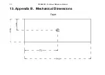
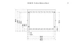
Page 34: ...30 MSD600M Technical Reference Manual 13 Appendix B Mechanical Dimensions...

Page 35: ...MSD600M Technical Reference Manual 31...

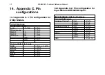
Page 36: ...3 AES 3 Hot Pin 9 Cold Pin 2 GND Pin 1 GND Pin 4 10 14 Appendix C Pin configurations 14 1 Appendix C 1 Pin configuration for Utility Module MSD600M Technical Reference Manual 32 UTILITY MODULE 9 Pole...

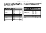
Page 37: ...LE 1 AES 3 2 Analogue 15 Pole DSUB Female Analogue Channel 1 Hot Pin 15 Cold Pin 8 GND Pin 7 Analogue channel 2 Hot Pin 14 Cold Pin 6 GND Pin 13 AES 3 Hot Pin 9 Cold Pin 2 GND Pin 1 GND Pin 4 10 INPUT...

Page 38: ...Pin 4 Bit 4 Key 4 Pin 16 Bit 5 Key 3 Pin 3 Bit 6 Key 2 Pin 15 Bit 7 Key 1 Pin 2 Gpio_1 Bit 8 Reset Reset Pin 22 Hold Hold Bit 9 Pin 9 Bit 10 Pin 21 Bit 11 Pin 8 Bit 12 Pin 19 Bit 13 Stop Pin 6 Bit 14...

Page 39: ...MSD600M Technical Reference Manual 35...

Page 40: ...itor the analogue inputs from module 1 36 STATUS DISPLAY REFERENCE CHART Preset No 0 Base Setup A B C D E F Line Output Input Line Input Ref 53 PHAS CH 1 57 CH 1 54 PHAS CH 2 58 CH 2 55 CENT OFF 56 C...

Page 41: ...atus Display Line Number Destination ID Column C Status Display Source ID Column D E Source Line Number Source ID Column F Shows the physical input connection corresponding to the line number in colum...

Page 42: ...RT Preset No 1 All Analogue A B C D E F Line Output Input Line Input Ref 53 PHAS CH 1 57 CH 1 54 PHAS CH 2 58 CH 2 55 CENT OFF 56 C 1 OFF 57 C 2 OFF 58 C 3 OFF 59 C 4 OFF 60 C 5 OFF 61 C 6 OFF 62 C 7...

Page 43: ...Status Display Line Number Destination ID Column C Status Display Source ID Column D E Source Line Number Source ID Column F Shows the physical input connection corresponding to the line number in co...

Page 44: ...LAY REFERENCE CHART Preset No 2 All AES A B C D E F Line Output Input Line Input Ref 53 PHAS CH 1 57 CH 1 54 PHAS CH 2 58 CH 2 55 CENT OFF 56 C 1 OFF 57 C 2 OFF 58 C 3 OFF 59 C 4 OFF 60 C 5 OFF 61 C 6...

Page 45: ...Status Display Line Number Destination ID Column C Status Display Source ID Column D E Source Line Number Source ID Column F Shows the physical input connection corresponding to the line number in co...

Page 46: ...nputs 1 and 2 from module I1 line 33 and 34 42 STATUS DISPLAY REFERENCE CHART Preset No 3 LR A B C D E F Line Output Input Line Input Ref 53 PHAS CH 1 57 CH 1 54 PHAS CH 2 58 CH 2 55 CENT OFF 56 C 1 O...

Page 47: ...Status Display Line Number Destination ID Column C Status Display Source ID Column D E Source Line Number Source ID Column F Shows the physical input connection corresponding to the line number in co...

Page 48: ...vector C 1 is coupled to the bargraph showing the information from the right channel Please observe that the two vectors C 2 and C 3 are both coupled to the information from the surround sound channe...

Page 49: ...Status Display Line Number Destination ID Column C Status Display Source ID Column D E Source Line Number Source ID Column F Shows the physical input connection corresponding to the line number in co...

Page 50: ...rgraph showing the informa tion from the right channel The next vectors are arranged clock wise to build the complete Jelly Fish sur round sound figure If you want to monitor 5 1 surround sound from a...

Page 51: ...Status Display Line Number Destination ID Column C Status Display Source ID Column D E Source Line Number Source ID Column F Shows the physical input connection corresponding to the line number in co...

Page 52: ...bargraph showing the centre information and vector C 1 is coupled to the bargraph showing the information from the right channel The next vectors are arranged clock wise to build the complete Jelly Fi...

Page 53: ...Status Display Line Number Destination ID Column C Status Display Source ID Column D E Source Line Number Source ID Column F Shows the physical input connection corresponding to the line number in co...

Page 54: ...tre information and vector C 1 is coupled to the bargraph showing the information from the right channel The next vectors are arranged clock wise to build the complete Jelly Fish surround sound figure...

Page 55: ...CH5 and CH6 and is not the normal Sum Difference signal If you want to monitor 7 1 surround sound from a digital signal source you must change lines 65 72 in column A B to the relevant digital inputs...

Page 56: ...vector C 1 is coupled to the bargraph showing the information from the right channel The next vectors are arranged clock wise to build the complete Jelly Fish surround sound figure If you want to mon...

Page 57: ...Status Display Line Number Destination ID Column C Status Display Source ID Column D E Source Line Number Source ID Column F Shows the physical input connection corresponding to the line number in co...

Page 58: ...audio inputs are from module I1 lines 33 and 34 The Jelly Fish figure is set up in the same way as in Preset 4 54 STATUS DISPLAY REFERENCE CHART Preset No 9 Lt Rt A B C D E F Line Output Input Line In...

Page 59: ...Status Display Line Number Destination ID Column C Status Display Source ID Column D E Source Line Number Source ID Column F Shows the physical input connection corresponding to the line number in co...

Page 60: ...MSD600M Technical Reference Manual 56...

Page 61: ...se this page instead Name Company Address Postcode City Country Phone Fax E mail Model No Unit Serial No Purchase Date Purchased from dealer Which features would you like to see in new ver sions of th...

Reviews: