background image

FlameWheel 450 

User Manual 

6


©

 2015 DJI. All Rights Reserved. 

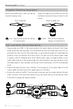
Propeller Mounting Description

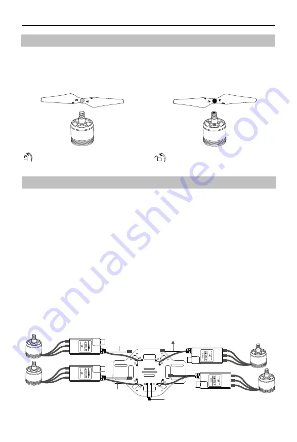
Attach the propeller with a silver nut onto the 
counter clockwise motor.

Attach the propeller with a black nut onto the 
clockwise motor (which has an indent on the 
screw).

Lock:  Tighten the propeller by rotating  
 

it in this direction. 

Unlock:  Remove the propeller by  
 

rotating it in this direction.

Black nut (9450 cw)

Silver nut (9450)

ESC and Motor Wiring Description

1. Please solder each ESC to the power pads on the bottom board as shown in the figure 

below. Make sure that the solder is firmly attached on the power pads and that there is no 
possibility for a short circuit. The power cable is a coaxial power cable. Do not damage the 
protector on the red cable to avoid short circuit. The red core of the coaxial power cable 
is positive, and the shielding layer of the coaxial power cable is negative. Make sure to 
solder them correctly at the proper length (the wires should be just long enough to reach 
the soldering point, face outwards, and should not be bunched up in front of the soldering 
point).

2. Connect the signal cable to your controller. The orange wire of the signal cable is for the 

control signal; the brown wire of the signal cable is for the GND.

3. Connect the motor to the ESC. Test the motor and make sure the rotation direction of each 

motor is correct. If not, switch the position of any two cables that are connecting the motor 
to the ESC to change the rotation direction.

+

_

+

_

+

_

+

_

+

_

Connect to the battery

Motor

Power cable

ESC

ESC cable

To the controller

Summary of Contents for FlameWheel 450

Page 1: ...FlameWheel 450 2015 05 Revision V2 2 User Manual ...

Page 2: ... trademarks of their respective owner companies This product and manual are copyrighted by DJI Innovations with all rights reserved No part of this product or manual shall be reproduced in any form without the prior written consent or authorization of DJI Innovations No patent liability is assumed with respect to the use of the product or information contained herein F450 Profile FlameWheel 450 F4...

Page 3: ...2 F450 Profile 2 Product Usage Cautions 2 Contents 3 In the Box 4 Tools Needed 5 Preparing for Mounting 5 Motor Mounting Description 5 Propeller Mounting Description 6 ESC and Motor Wiring Description 6 Assembly 7 ESC Sound Description 8 Specifications 8 ...

Page 4: ...450FBT 1 Bottom Board 450FBB 1 Frame Arms 450FAC 2 Frame Arms 450FAW 2 Motors CW 2 Motors CCW 2 Propeller Pairs 3 ESC 4 Screws 450 M3 8 16 Screws 450 M2 5 6 24 Propeller Removal Clamp 1 Magic Strap 450MSX 1 Battery Band 450BBX 11 Power Line Pair 450PLP 1 ...

Page 5: ...e Scissors Diagonal Cutting Pliers For binding devices and wires Foam Double Sided Adhesive Tape For fixing receiver controller and other modules Soldering iron wires For connecting ESCs power cables to bottom board The screw size is M3 Mount the motors using appropriate screws Note the thread depth and the size of the screws Using screws that are too long or too large may damage the motor 19 mm 1...

Page 6: ...s a coaxial power cable Do not damage the protector on the red cable to avoid short circuit The red core of the coaxial power cable is positive and the shielding layer of the coaxial power cable is negative Make sure to solder them correctly at the proper length the wires should be just long enough to reach the soldering point face outwards and should not be bunched up in front of the soldering po...

Page 7: ...all ESCs and motors Make sure the rotation direction of each motor is the same as the way in the figure shows If not switch any of two wire connections of the incorrect motor to change its rotation direction 4 Tidy all cables Make sure all cables are not be cut by the frame boards and propellers Smooth out the boards edge if necessary 5 Install the top board 6 Install the propellers Please install...

Page 8: ...wable Voltage 17 4 V Max Allowable Current Persistent 20 A Max Allowable Peak Current 3 seconds 30 A PWM Input Signal Level 3 3 V 5 V Compatible Signal Frequency 30 Hz 450 Hz Battery 3 S 4S LiPo Weight without cable 12 5 g Weigh with cable 27 g Motor Stator size 23 12 mm KV 960 rpm V Weight 57 g Propeller Diameter Thread Pitch 24 12 7 cm 9 4 5 0inch Weight Single 13 g Normal Description 1234 Ready...

Page 9: ...t to change Download the latest version from http www dji com product flame wheel arf If you have any questions about this document please contact DJI by sending a message to DocSupport dji com 2015 DJI All Rights Reserved ...

Reviews: