Dixon ZTR 501 Operator'S Manual Download Page 32

  
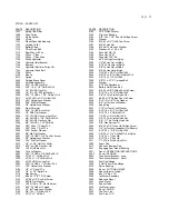
ZTR 501 - PARTS LIST 
  
PART#  DESCRIPTION 
1657 

Spring - Belt Idler 

1668 

Drive Pulley 

1675 

Clutch Anchor 

1682 

L-Rod 

1701 

Wheel/Deck Hub Bearing 

1702 

Locking Collar 

1712 

Battery Strap 

1714 

T-Box Drive Belt 

1715 

Rear Wheel & Tire 

1732 

Pulley - T-Box 

1733 

Pulley - T-Box Drive 

1734 

Pulley Hydrostat 

1739 

Hydrostat Idler Bracket 

1742 

Bumper 

1743 

Hydrostat Flat Idler Pulley HO 

1744 

Hydrostat Drive Belt 

1745 

Pulley 

2128 

Sleeve 

2414 

Spring 

2460 

Parking Brake Decal 

2823 

Oil Drain Assembly 

3005 

5/16"-18 UNC Hex Nut 

3006 

5/16"-18 x 1 1/4" HH Bolt Gr 5 

3007 

1/4"-20 UNC Hex Nut 

3008 

1/4" ID x 3/4" 00 Flat Washer 

3009 

5/16"-18 UNC x 1 3/4" HH Bolt Gr 5 

3014 

l/4"-20 UNC x 3/4" HH Bolt Gr 5 

3019 

5/16" Helical Lock Washer 

3020 

5/16" Std Flat Washer 

3023 

1/4" Helical Lock Washer 

3029 

Front Grommet 

3031 

5/16"-18 UNC Acorn Nut 

3033 

1/2" SAE Flat Washer 

3035 

1/2"-13 UNC Hex Jam Lock Nut 

3037 

3/8"-24 UNF x I 1/4" HH Bolt Gr 5 

3047 

3/8"-24 UNF Hex Lock Nut 

3048 

3/8"-16 UNC x 1 i/2" HH Bolt 

3052 

3/32" Dia x 1" Cotter P1n 

3054 

3/16" Dia x 1" Roll P1n 

3056 

5/16" Fender Washer 

3057 

3/8" Std Flat Washer 

3061 

5/16"-18 UNC 1 3/4" Soc Set Screw 

3065 

3/8" Helical Lock Washer 

3066 

3/16" Std Flat Washer 

3072 

1/8" x 1 3/4" Hatr Pin Cotter 

3074 

5/16"-24 UNF Hex Jam Nut 

3081 

16-32 UNC Hex Nut 

3082 

16 Lock Washer 

3087 

5/16"-18 UNC x 3/4" HH Bolt Sr S 

3088 

l/4"-20 x 1" HH Bolt Gr 5 

3090 

l/4"-20 x 1 1/4" HH Bolt Gr 5 

3091 

l/4"-20 UNF Hex Lug Nut 

3093 

5/16"-18 UNC x 1" HH Bolt Gr 5 

3101 

7/16" Helical Lock Washer 

3106 

1/4" x 1" Spirol P1n 

3107 

1/4" x 1 1/2" Spiral Pin 

3118 

Disc Spring 

3133 

#8-32 x 1 1/2" TR 3 Screw 

3134 

l/4"-28 x 1/4" Soc Set Screw 

3145 

#6 Std Flat Washer 

3151 

16-32 UNC x 1/2" Rd Hd Screw 

3161 

5/16"-24 UNF LH Thread 

3163 

1/2" Int Tooth Lock Washer 

3169 

3/8"-16 x 1" HH Bolt Gr 5 

3174 

l/2"-13 x 1" HH Bolt 
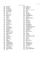
PART#  DESCRIPTION 
3180 

l/4"-2Q Hex Locknut 

3182 

Flip Lock Bushing 

3184 

5/l6"-18 x 1 1/4" Pan Hd Phillips Screw 

3185 

Washer 

3186 

#12-24 x 3/4" Drill & Tap Screw 

3187 

#10-32 Hex Nut 

3188 

#10 Ext Tooth Lock Washer 

3193 

Washer .43 x 1.38 x .25 

3194 

Face Nut 5/8"-32 

3195 

Face Nut l/2"-27 

3196 

Face Nut 7/16"-28 

3198 

l/4"-20 Wing Nut w/Nylok 

3204 

1/4"-20 Hex Nut w/Nylok 

3205 

5/16"-18 Hex Nut w/Nylok 

3206 

3/8"-16 Hex Nut w/Nylok 

3208 

#10-24 Hex Nut w/Nylok 

3220 

7/16"-20 x 2 3/4" HH Bolt Gr 5 

3224 

5/8"-18 x 3/4" HH Bolt w/Nylok Gr 5 

3225 

3/8"-16 x 2 1/4" HH Bolt 

3228 

5/B"-11 x 6 1/4" Carriage Bolt 

3229 

Washer 

3231 

9/16" Std Flatwasher 

3233 

Battery Hold Down Bolt 

3235 

#10-24 x 5/8" Phillips Pan Hd Screw 

3243 

5/16"-18 x 3 1/4" HH Bolt Gr 5 

3245 

3/8"-16 Thin Profile Nylok Nut 

3247 

#6-20 x 1/2" Phillips Pan Hd Screw 

3248 

5/16" ID x 1/8" Thick Washer 

3249 

5/8" Int Tooth Lock Washer 

3256 

Snap Ring 

3257 

7/16" Int Tooth Lock Washer 

3258 

5/16"-18 x 4 1/2" HH Bolt Gr 8 

3259 

5/16"-18 x 5" HH Bolt Gr 8 

3260 

1/4”-20 x 1/2" HH Bolt Gr 5 

3262 

3/4”-10 Thin Profile Nylok Nut 

3263 

5/8”--11 Thin Profile Nylok Nut 

3264 

5/I6" Disc Spring HD 

3265 

#10-24 x 3/4" Truss Hd Phillips Screw 

3266 

1/4” Int Tooth Lockwasher (Not Shown) 

3267 

5/16"-18 x 1 3/8" HH Bolt Gr 5 

3268 

3/8"-24 x 1 1/4" HH Bolt Gr 8 w/Nylok 

3269 

5/16"-18 x 1" Soc HB 

3270 

5/16"-18 x 3" Soc HB 

3271 

1"-14 Thin Profile Nylok Nut 

3300 

Foam Pad 

3511 

Adhesive Bumper Pad 

3521 

Engaging Cam Mount Bushing 

3531 

Decal - OPERATING INSTRUCTIONS 

3S36 

Decal - DANGER 

3552 

Tank Mount Bracket - Long 

3553 

Tank Mount Bracket - Short 

3554 

Fuel Cap/Guage 

3558. 

2 Gal Tank w/Cap-Gauge 

3578 

Nylon Bushing 

3585 

Decal - CUTTING HEIGHT 

3589 

Spacer (Electic Clutch) 

3590 

Key 1/4" Sq x 1/2" 

3599 

Iso Mount Assembly 

3600 

Rebound Mount 

3601 

Load Mount 

3602 

Spacer Tube 

3603 

Iso Mount Insert 

3617 

Decal - DIXON 

3635 

Tee-Fuel Line 

3644 

Fuel Line 7 1/2" 

Page 29


Summary of Contents for ZTR 501

Page 1: ......

Page 2: ... 3 SPECIFICATIONS Page 5 4 SET UP AND SERVICE Pages 6 1 1 5 OPERATION INSTRUCTIONS Pages 12 13 6 CARE AND MAINTENANCE Pages 14 21 7 TROUBLESHOOTING Pages 22 24 8 PARTS ILLUSTRATIONS Pages 25 28 9 PARTS LIST Pages 29 31 10 ELECTRICAL SCHEMATIC Page 32 ...

Page 3: ...ou start to use the mower read the operator s manual carefully and become completely familiar with the controls The information in this operator s manual applies to all Dixon ZTR Model 501 Mowers Your Dixon dealer will gladly provide a check out ride and answer any questions See your dealer for warranty service parts and repairs DIXON INDUSTRIES INC Box 494 Coffeyville Kansas 67337 0494 ...

Page 4: ...phill Mow slopes when the grass is dry and watch for bumps holes and other obstacles Test the slope with the blades off A good rule of thumb is Don t mow on a slope you can t back up Stay clear of drop offs especially if they are on the down side of a slope 4 THROWN OBJECTS The fast spinning mower deck blade can strike stones or other objects which can be hurled into the path of a bystander To pre...

Page 5: ...ped with a weight sensitive switch that kills the engine when operator leaves the seat while blades are engaged Test this important safety feature before each time mower is used This may be done by starting engine engaging blades and then rising slightly from seat If engine does not stop see your dealer for necessary repair 10 Before adjusting or servicing your mower turn off the engine and let it...

Page 6: ... is in safe working condition 20 To reduce fire hazard keep the engine free of grass leaves or excessive grease 21 The mower should be stopped and inspected for damage after striking a foreign object or if it starts vibrating and any damage should be repaired before restarting and operating the mower 22 When mowing proceed as follows A Mow only in daylight or in good artificial light B Shut the en...

Page 7: ...ility for either the policies or procedures of said manufacturers 3 BELTS AND BLADES Our warranty does not apply to the blades or belts used on our mowers due to the very nature of the function they perform and to h the elements they are exposed to 4 ROUTINE MAINTENANCE Adjustments or any type of oil or grease used on the mower 5 TIRES Warranty extended by tire manufacturer 6 PEERLESS GEAR BOX War...

Page 8: ...aides discharge of grass Blade Drive Warner electric clutch Drive System 2 Sundstrand BDU 10 L hydrostatic transmissions driven by a permanently lubricated peerless gear box Engine 18 HP Briggs and Stratton twin cylinder 1C with cast iron sleeves and ducted air flow Starting System Electric by key switch operation with safety interlocks on parking brake and blade drive clutch Tires Front 11 x 4 10...

Page 9: ...Page 6 SET UP AND SERVICE 1 Seat assembly instructions 2 Upper control lever installation 3 Mower deck installation 4 Deck leveling procedure 5 Final preparation ...

Page 10: ...e 2 rear studs of the seat slide into the rear holes of the body cover Firmly hold seat assembly against body cover with one hand while rear body is raised to fully open position Continue to hold seat against body to prevent damage to seat safety switch wiring 4 Install 1 flat washer and 1 nylok nut on 1 of the rear studs extending through body cover and seat frame tighten a few threads to hold se...

Page 11: ...rt left upper control lever on swivel plate 3 Install fiber washer and jam nut 4 Proper tightness or tension on jam nut is achieved when swing out movement of upper control levers requires some pressure Levers should not fall to the side or be sloppy in movement 5 Repeat procedure on right side ...

Page 12: ...his will allow for belt installation in step 7 6 Raise mower deck at the rear and slide 1 of the deck support rods through the mower deck lift plate and the tabs of the mower deck Note A length of 2 x 4 board turned on end and placed under the mower deck for support will make this task easier if the installation is being done by one person due to the weight of the mower deck 7 Raise front of mower...

Page 13: ...s measurement Move to the opposite side and check that measurement is the same If adjustment is required turn the nut on the bottom of the front threaded adjuster up or down until both side to side measurements are equal Retain measurement D Rotate or turn both outer blades to align with the deck in a front to rear manner Move to the left rear threaded adjuster left rear is designated from operato...

Page 14: ...d be completed using engine service manual provided with mower Initial Start and Hydrostat Transmission Check 1 Final hydrostat checks have been performed at the factory however it is necessary to check that the pressure relief bypass on each hydrostatic transmission is completely released before attempting to drive mower 2 Each hydrostat has a bypass relief pin located at the bottom front of the ...

Page 15: ...onfidence necessary to mow like a pro LEVER MOVEMENTS No shifting or clutching required TO GO FORWARD Release parking brake From neutral position gently puch both drive levers forward to increase speed move levers farther forward TO GO BACKWARD From neutral position gently pull both drive levers toward you TURNING Turning is controlled by moving one drive lever slightly forward or rearward of the ...

Page 16: ... in a non mowing situation Located in front of operator on the right side of mower BLADE DRIVE To engage the mower deck cutter blades lift switch up lightly and push forward To disengage blades pull switch backward Switch is clearly marked on and off LIGHT SWITCH The headlights are activated by pushing the switch forward Failure to turn off the lights once the engine is stopped will result in rapi...

Page 17: ... accurately perform all service required Due to the precision nature of these transmissions field repairs cannot be recommended MAINTENANCE SCHEDULE To insure a long and trouble free service life on all the components used on the Model 501 a regular and thorough maintenance schedule should be followed As with any type of precision made equipment a certain amount of initial bedding in or seating of...

Page 18: ...emoved Slide deck from under chassis 3 Reverse procedure to re install deck assembly CUTTER BLADE REMOVAL 1 Carefully place deck assembly in a manner which will allow access to the blade bolts Hold blade from turning while bolt is removed from the center of each hub assembly Caution wear heavy thick gloves when holding onto cutter blade avoid the sharp edge of the blade 2 When re assembling blades...

Page 19: ...k nuts NOTE Cable must have the above dimension with parking brake released or drive belt may slip causing a loss of power Step 6 Neutral adjustment must be checked at this time which will require the engine to be started and the parking brake released Swing upper control levers outward and into neutral slots start engine use caution when releasing parking brake as mower may tend to creep or move ...

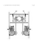
Page 20: ... 1 HYDROSTAT MOUNTING BOLTS 2 THREADED ADJUSTERS TO TENSION CHAINS Page 17 ...

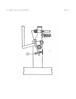
Page 21: ... 1 ADJUSTMENT POINTS FOR T BOX BELT TENSION Page 18 ...

Page 22: ... 1 Forward lever stop adjustment Page 19 ...

Page 23: ...ter DRIVE CHAINS Primary and final drive RECOMMENDED LUBRICANT Name brand aerosol chain spray SERVICE INTERVALS As required for operating conditions Remove excess dirt from chains lubricate each chain completely by applying the lube to the inside of each connecting link Applying lube directly to the top of the chain will only allow the lube to be thrown off in operation The chains are of special c...

Page 24: ...nd dirt build up Avoid directing water pressure onto the mower deck hub assemblies electrical wiring and engine components such as air filter openings Never wash or clean the Sundstrand BDO 10 L hydrostatic transmissions as damage to these units could result To remove excess water which accumulates during washing of the mower either blow off with compressed air if available or start the engine all...

Page 25: ...Dixon ZTR Dealer is also available to provide assistance to you SITUATION CAUSES REMEDY Poor cut quality Ground speed Reduce mowing speed Poor cut quality Loose belts Adjust per operators manual Poor cut quality Engine RPM too low Increase engine RPM to Poor cut quality Dull or bent blades Sharpen or replace as required Poor cut quality Unlevel mower deck Adjust per operators manual Poor cut quali...

Page 26: ...er operators manual Consult your dealer for repair Loss of power on both wheels after being operated for a length of time Belt from engine to T Box is slipping Adjust per operators manual Consult your dealer for reoair Operation of mower Review operators section of owners manual TROUBLE SHOOTING Page 23 DRIVE SYSTEM Poor driving performance Oil leaks Tighten or replace as required Loose or missing...

Page 27: ...tric clutch will not engage mower deck blades Head lights do not operate Low battery condition Poor connections on clutch switch Broken wiring Poor connection on lights Broken wiring Bad bulb Repair or replace as required Consult your dealer for repair Repair or replace as required Note Electrical system failures are generally simple in nature always check the obvious first and then move onto the ...

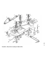
Page 28: ...Illustration Mower Deck Assembly 50 Model 501 ...

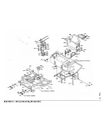
Page 29: ...Illustration Body Assembly Model 501 ...

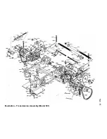
Page 30: ...Illustration Transmission Assembly Model 501 ...

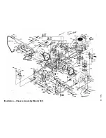
Page 31: ...Illustration Chassis Assembly Model 501 ...

Page 32: ...h Lock Washer 3169 3 8 16 x 1 HH Bolt Gr 5 3174 l 2 13 x 1 HH Bolt PART DESCRIPTION 3180 l 4 2Q Hex Locknut 3182 Flip Lock Bushing 3184 5 l6 18 x 1 1 4 Pan Hd Phillips Screw 3185 Washer 3186 12 24 x 3 4 Drill Tap Screw 3187 10 32 Hex Nut 3188 10 Ext Tooth Lock Washer 3193 Washer 43 x 1 38 x 25 3194 Face Nut 5 8 32 3195 Face Nut l 2 27 3196 Face Nut 7 16 28 3198 l 4 20 Wing Nut w Nylok 3204 1 4 20 ...

Page 33: ...gine Wire Assembly 4453 Access Cover Assembly 5028 Bearing PART DESCRIPTION 5070 Key 3 16 Sq x 7 8 5085 Brake Band 5087 Spacer 3 8 x 1 2 5101 Brake Link 5112 Key Sq 3 16 x 1 1 2 Fits 5110 5170 Spring 5189 Bushing 5500 T Box 5501 Mount Plate 5502 Mount Shim 5503 T Box Guide Left 5504 T Box Guide Right 5507 Brake Plate Bracket Left 5508 Brake Plate Bracket Right 5510 Sprocket 10T 5511 Sprocket 30T 5...

Page 34: ...020 Caster 9022 Caster Axle Bushing 9023 Engine Mount Plate Fwd 9024 Engine Mount Plate Rear 9031 Spacer 9035 Lift Frame 9049 Lift Bushing Bracket 9055 Lift Cam Left 9056 Lift Cam Right 9057 Lift Rod 9065 Lift Handle 9066 Lift Shaft 9067 Control Rod 9076 Seat Frame Cable 9082 Seat Frame Pivot Rod 9088 Caster Wheel Tire 9089 Control Rod Assembly 9098 L Rod 9 16 x 15 3 16 9104 Control Panel 9110 Tan...

Page 35: ......

Reviews: