background image

English

-

53

7.

Drain old oil filters of all free flowing oil prior
to disposal. Place used oil in appropriate
containers and dispose of it in accordance
with laws in your area.

8.

Remove the top port plug (see illustration)
from the left side and right side of the
transaxles prior to filling with oil. This will
allow the transaxles to vent during oil fill.

9.

Remove the cap from the transaxles’
expansion tank located on the vehicle
frame.

10. Fill with 20W50 motor oil until oil just

appears at the bottom of each transaxles’
top port (approximately 2 quarts per
transaxle, 4 quarts total). Install the top port
lug into each transaxle as the oil level
reaches this port.

11. Install and torque the top port plugs to 180

in./lbs.

12. Continue to fill the transaxles through the

expansion tank until the “Full Cold” line is
reached (this will take approximately 23
additional ounces).

13. Re-install the expansion tank cap by hand.

Be careful to not overtighten.

14. Proceed to the purge procedure.

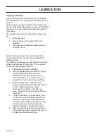
1. Filter

2. Top Port Plug

3. Filter Guard

4. Screws

Changing the oil filter

8019-010

1

3

4

2

1

3

2

Expansion Tank

1. Expansion Tank

2. Cap

3. Transaxles

8019-012

LUBRICATION

Summary of Contents for BLACK BEAR 34/ 968999564

Page 1: ...ator s Manual ZTR34 968999564 ZTR44 968999565 ZTR34 968999566 ZTR34 968999618 ZTR34 968999619 ZTR44 968999690 ZTR34 968999731 Please read the operator s manual carefully and make sure you understand t...

Page 2: ...er the influence of any mind altering substance WARNING Engine exhaust some of its constituents and certain vehicle components contain or emit chemicals known to the State of California to cause cance...

Page 3: ...le 34 Battery 36 Ignition System 37 Checking Safety System 37 Checking Engine s Cooling Air Intake 38 Checking Adjusting Throttle Cable 38 Checking Adjusting Choke Cable 38 Replacing Air Filter 39 Rep...

Page 4: ...ad traffic regulations before transporting on public roads If the machine is transported you must always use approved fastening equipment and ensure that the machine is well anchored DO NOT operate th...

Page 5: ...umber The machine s manufacturing number can be found on the printed plate affixed to the left in the engine compartment Stated on the plate from the top are The machine s type designation I D The man...

Page 6: ...ial for misuse or misassembly WARNING Xxxx xxxxxx xxxxx xxxx xxxxxxxxx xxxxxx xxxxxxxxx xx xxxxxxxx xxxx xxxxxx IMPORTANT INFORMATION Xxxx xxxxxx xxxxx xxxx xxxxxxxxx xxxxxx xxxxxxxxx xx xxxxxxxx xxxx...

Page 7: ...from no greater Manual performing any the machine than 10 maintenance or repair work Whole body Severing of fingers Do not open or Careful backing up Careful going exposure to and toes remove safety w...

Page 8: ...he instructions to operate the machine Clear the area of objects such as rocks toys wire etc which could be picked up and thrown by the blades Be sure the area is clear of bystanders before operating...

Page 9: ...These operators should evaluate their ability to operate the riding mower safely enough to protect themselves and others from serious injury Follow the manufacturer s recommendation for wheel weights...

Page 10: ...s rocks or other hidden objects Uneven terrain could overturn the machine Tall grass can hide obstacles Choose a low ground speed so that you will not have to stop while on the slope Do not mow on wet...

Page 11: ...ildren out of the mowing area and in the watchful care of a responsible adult other than the operator Be alert and turn machine off if a child enters the area Before and while backing look behind and...

Page 12: ...t on the ground If this is not possible then refuel such equipment with a portable container rather than from a gasoline dispenser nozzle Keep the nozzle in contact with the rim of the fuel tank or co...

Page 13: ...odify safety equipment Check regularly to be sure it works properly The machine must not be driven with defective or unmounted protective plates protective cowlings safety switches or other protective...

Page 14: ...protective goggles Ensure that the fuel filler cap is mounted tightly and no flammable substances is stored in an open vessel Never work with the starter circuit if there is spilled fuel Disconnect th...

Page 15: ...fasten the machine with approved fastening devices such as bands chains or straps when transporting Do not operate this machine on public roadways Check and abide by local traffic regulations before...

Page 16: ...damaged the entire ROPS must be replaced Check all bolts including seat belt for correct torque before each use Check ROPS structure for damage before each use ROPS bar is NOT intended for use in sub...

Page 17: ...ydraulic pumps which in turn drive a hydraulic motor for each drive wheel Using the left and right steering controls the flow is regulated and thereby the direction and speed 1 Motion Control Levers 2...

Page 18: ...ieved by moving one control backward behind the neutral position and carefully moving the other steering control forward from its neutral position The rotation direction when zero turning is determine...

Page 19: ...the seat on the front side of the hydro pumps Raise the deck into the highest cutting position Lift the seat frame assembly to access the release valves Use a 5 8 wrench to rotate bolt counter clockwi...

Page 20: ...ot store spill or use gasoline near an open flame IMPORTANT INFORMATION Experience indicates that alcohol blended fuels called gasohol ethanol or methanol can attract moisture which leads to separatio...

Page 21: ...ng the throttle control all of the way forward will choke the engine 8 Throttle Control The throttle control regulates the engine speed and thereby the rate of rotation of the blades assuming the blad...

Page 22: ...brake is found on the operator s left Pull the lever upward to activate the brake and downward to release it The park brake is designed to hold the mower from moving and is not intended for use in sto...

Page 23: ...he trigger and moving the lever forward Set the desired cut height with pin The cutting height range is from 1 38 mm to 5 140 mm in 13 mm increments The heights are measured from the ground up to the...

Page 24: ...nit under its own power the operator must be in the seat start engine see Before Starting in Operation section adjust engine speed to idle disengage parking brake do not engage blades at this time rot...

Page 25: ...engine can be started The driver must be seated on the seat The blade switch for engaging the mower blades must be depressed The parking brake must be on Both steering controls must be in the locked...

Page 26: ...tle to the middle position If the engine is cold the throttle control should be pushed forward to its choke position Press in and turn the ignition key to the start position Steering controls in the o...

Page 27: ...turn to run position 8050 781 STOP IMPORTANT INFORMATION Do not run the starter for more than 5 seconds each time If the engine does not start wait about 10 seconds before retrying Set the engine spee...

Page 28: ...the other end of the BLACK cable to a good CHASSIS GROUND on the mower with the discharged battery away from the fuel tank and battery To remove cables reverse order Remove BLACK cable first from chas...

Page 29: ...lling out the blade switch 5 Move throttle control to full throttle not choke 6 The machine s speed and direction are continuously variable using the two steering controls When both controls are in th...

Page 30: ...speed possible should be used before starting up or down hills Avoid stopping or changing speed on hills If stopping is absolutely necessary pull drive levers into the neutral position and push to the...

Page 31: ...he lawn becomes more even and the grass clippings more evenly distributed over the mown area The total time taken is not increased as a higher operating speed can be used without poor mowing results A...

Page 32: ...essing the pedal forward to the transport position When the machine is standing still activate the parking brake by pulling the lever upward Move the throttle to the minimum position tortoise symbol T...

Page 33: ...hydro pumps Raise the deck into the highest cutting position Lift the seat frame assembly to access the release valves Use a 5 8 wrench to rotate bolt counter clockwise two full turns to disengage pu...

Page 34: ...z Clean the air cleaner s pre filter 2 foam z z Clean the air cleaner s filter cartridge 2 paper filter z z Check adjust the parking brake Inspect muffler spark arrester Maintenance Schedule The follo...

Page 35: ...g fins 2 Replace the air cleaner s pre filter 2 foam z z Check adjust the mower deck z z Check the engine valve clearance 3 Perform the 300 hour service 3 1 First change after 5 8 hours When operating...

Page 36: ...Position deck to lowest setting 5 Front underside of frame remove the nuts that secure the battery hold down 6 Carefully remove the battery from the mower 7 Install new battery with terminals in the...

Page 37: ...ystem The machine is equipped with a safety system that prevents starting or driving under the following conditions The engine can only be started when The mower deck is disengaged The steering contro...

Page 38: ...ed in the correct hole in the lower lever see illustration 3 Push the throttle cable s outer casing as far to the left as possible and tighten the clamping screw Checking and Adjusting the Choke Cable...

Page 39: ...ed out as follows 1 Remove the plastic fastener on the top of the air filter cowling and remove the air filter cowling 2 Remove the foam rubber pre filter and clean using a mild detergent Squeeze it d...

Page 40: ...he hose clamps away from the filter Use flat nosed pliers 2 Pull the filter loose from the hose ends 3 Push the new filter into the hose ends Position the filter with the FLOW arrow pointing up toward...

Page 41: ...hours of operation Check for severe cracking and large nicks NOTE The belt will show some small cracks in normal operation Belt tension is manually adjustable Turn bolt on deck eyebolt to adjustment t...

Page 42: ...ine shaft 2 Route the belt forward between the EZT E Series Zeroturn Transaxles and up onto the deck 3 Place belt around spring loaded idler pulley 4 Wrap the belt around the stationary idler pulley a...

Page 43: ...ign the clutch anti rotation tab into slot on clutch Secure clutch install wire Reinstall the deck belt onto the electric clutch belt see Deck Belt Removal in this section of the manual Checking the B...

Page 44: ...n blade bolt securely Torque blade bolt to 27 35 ft lb 35 45 Nm WARNING Blades are sharp Protect your hands with gloves and or wrap blades with a heavy cloth when handling 1 Blade 2 Center hole 3 Cutt...

Page 45: ...the key 4 Make sure the blades and all moving parts have completely stopped 5 Disconnect the spark plug wire from all spark plugs and place the wire where it cannot come in contact with the plug WARNI...

Page 46: ...st all of the anti scalp rollers to the same position Be sure to readjust the anti scalp rollers if the cutting height is changed 3 Turn both outer blades to align with the deck in front to rear manne...

Page 47: ...he two screws holding the cooler unit to the blower housing 3 Tilt the cooler downward 4 Clean the inside of the cooler with a brush or with compressed air 5 Reinstall the oil cooler to the blower hou...

Page 48: ...pe away excess grease after lubrication It is important to avoid getting lubricant on the belts or the drive surfaces on the belt pulleys Should this happen attempt to clean them with spirits If the b...

Page 49: ...ccordance with the Lubrication Schedule 1 Front Wheel Mount Lubricate with a grease gun one zerk for each wheel mount until the grease is forced out Use only good quality bearing grease Grease from we...

Page 50: ...out into the container 5 Then close the oil drain valve 6 Replace the oil filter if necessary 7 Fill with new engine oil in accordance with Checking the Oil Level 8 Start the engine Run it for a few...

Page 51: ...ng the ADD mark fill the oil to the FULL mark on the dipstick Never fill to above the FULL mark The oil is filled through the hole for the dipstick API class SF SG SH SJ or higher must be used Synteti...

Page 52: ...dure can be performed with the transaxles installed in the vehicle and the vehicle on level ground Apply the bypass valve for each transaxle and lock the vehicle parking brake 1 Remove the three 1 4 f...

Page 53: ...l just appears at the bottom of each transaxles top port approximately 2 quarts per transaxle 4 quarts total Install the top port lug into each transaxle as the oil level reaches this port 11 Install...

Page 54: ...off the ground Then repeated under normal operating conditions 1 Disengage the brake if activated 2 With the bypass valve open and the engine running at fast idle slowly move the directional control...

Page 55: ...al cable connections Fuse blown Ignition system faulty Fault in the starter safety circuit See Checking the Safety System in the Maintenance Section The engine runs rough Faulty carburetor The choke c...

Page 56: ...ff Air trapped in hydraulic system Mower deck not engaging Drive belt for the mower deck has come loose Contact for the electromagnetic coupling has loosened The blade switch is faulty or has come loo...

Page 57: ...des The suspending for the mower deck is uneven The chain fixture has come loose The blades are blunt Driving speed too high The grass is too long Grass collected under the mower deck The machine vibr...

Page 58: ...rs and far away from open flame Never use gasoline for cleaning Use a degreaser and warm water instead To ready the machine for storage follow these steps 1 Thoroughly clean the machine especially und...

Page 59: ...ODELS CODE COLOR A RED B RED C RED D BLLUE E BLUE F WHITE G WHITE H WHITE J WHITE K WHITE L WHITE M WHITE N RED WHT P RED WHT R YELLOW S YELLOW T YELLOW U YELLOW V YELLOW W GREEN X GREEN Y GREEN Z WHT...

Page 60: ...9618 REAR HARNESS MODELS 968999566 968999619 G F E M L M A H J A B K D D B C L H K C G J E CODE COLOR A RED B RED C RED D RED WHT E WHITE F WHITE G WHITE H WHITE J YELLOW K YELLOW L GREEN M BLUE CODE...

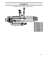
Page 61: ...English 61 SCHEMATIC REAR WIRING HARNESS MODELS 968999690 968999731 CODE COLOR A RED B RED C WHITE D WHITE E WHITE F BLUE G GREEN H YELLOW J RED WHT...

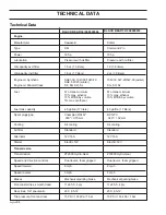
Page 62: ...tank capacity 4 5 gallon 17 liters 4 5 gallon 17 liters Spark plugs gap RC12YC RC12YC 040 1 02 mm 040 1 02 mm Cooling Air cooling Air cooling Air filter Standard Standard Alternator 12V 16A 12V 16A S...

Page 63: ...gagement Electric clutch Electric clutch Deck construction 7 gauge w 7 gauge skirts 7 gauge w 7 gauge skirts Productivity Productivity 2 75 acres hr 3 56 acres hr Overall dimensions Weight 650 lbs 295...

Page 64: ...l tank capacity 4 5 gallon 17 liters 4 5 gallon 17 liters Spark plugs gap Champion RCJ8Y RC12YC 030 0 75 mm 040 1 02 mm Cooling Air cooling Air cooling Air filter Standard Standard Alternator 12V 16A...

Page 65: ...nt Electric clutch Electric clutch Deck construction 7 gauge w 7 gauge skirts 7 gauge w 7 gauge skirts Productivity Productivity 2 75 acres hr 2 75 acres hr Overall dimensions Weight 650 lbs 295 kg 65...

Page 66: ...k capacity 4 5 gallon 17 liters 4 5 gallon 17 liters Spark plugs gap Champion RCJ8Y Champion RCJ8Y 030 0 75 mm 030 0 75 mm Cooling Air cooling Air cooling Air filter Standard Standard Alternator 12V 1...

Page 67: ...t Electric clutch Electric clutch Deck construction 7 gauge w 7 gauge skirts 7 gauge w 7 gauge skirts Productivity Productivity 2 75 acres hr 3 56 acres hr Overall dimensions Weight 650 lbs 295 kg 675...

Page 68: ...ax methanol Fuel tank capacity 4 5 gallon 17 liters Spark plugs gap Champion RXJ8Y 030 0 75 mm Cooling Air cooling Air filter Standard Alternator 12V 16A Starter Electric 12V Transmission Transmission...

Page 69: ...Hour meter Standard Blade engagement Electric clutch Deck construction 7 gauge w 7 gauge skirts Productivity Productivity 2 75 acres hr Overall dimensions Weight 650 lbs 295 kg Base machine length 71...

Page 70: ...t lb 110 Nm When this product is worn out and no longer used it should be returned to the reseller or other party for recycling In order to implement improvements specifications and designs can be alt...

Page 71: ...ecial requirements for any of the states Californian emission rules etc Do not remove any of these labels Certificates can also be supplied with the machine at delivery or written in the Engine manual...

Page 72: ...Check the mower deck adjustment 11 Check The safety switch for the parking brake The safety switch for the mower deck The safety switch in the seat The safety switch in the steering controls Parking b...

Page 73: ...English 73 SERVICE JOURNAL After the First 5 8 Hours 1 Change engine oil...

Page 74: ...ervice 1 Check the fuel pump s air filter 2 Sharpen Replace mower blades if required 3 Check the tire pressures 4 Check battery with cables 5 Lubricate according to lubrication chart 6 Check clean the...

Page 75: ...ign 50 Hour Service 1 Perform the 25 hour service 2 Clean replace the air cleaner s filter cartridge paper filter shorter intervals for dusty operating conditions 3 Change engine oil 4 Lubricate accor...

Page 76: ...orm the 50 hour service 3 Change the engine oil filter 4 Clean replace the spark plugs 5 Replace the fuel filter 6 Clean the cooling fins on the engine and transmission 7 Check V belts 8 Check tighten...

Page 77: ...as to which additional work is to be carried out 2 Perform the 25 hour service 3 Perform the 50 hour service 4 Perform the 100 hour service 5 Check adjust the mower deck 6 Clean the combustion chamber...

Page 78: ...the air filter s paper cartridge 4 Change the engine oil 50 hours 5 Replace the engine oil filter 100 hours 6 Check adjust the cutting height 7 Check adjust the parking brake 50 hours 8 Clean Change...

Page 79: ...English 79 SERVICE JOURNAL Action Date mtr reading stamp sign...

Page 80: ...Part No 539 118101 R01 08 14 07...

Reviews: