background image

Read “Safety Instructions” section and following 
pages, if you are unfamiliar with the machine.

Training

Zero turn mowers are far more maneuverable than 
typical riding mowers due to their unique steering 
capabilities. 
We suggest that this section be reviewed in its entirety 
prior to attempting to move the mower under its own 
power. Additionally, we suggest when first operating 
the mower, use a reduced throttle speed and reduced 
ground speed by NOT moving control levers to the 
furthest forward or reverse positions during initial 
operation, or until operator becomes comfortable 
with controls. We also suggest first time users, or new 
users to Zero Turn mowers to become familiar with 
the mower’s movement on a hard surface, such as 
concrete or blacktop PRIOR to attempting to operate 
on turf. Until operator becomes comfortable with 
mower controls and zero turning capability, they may 
damage turf due to overly aggressive maneuvers.

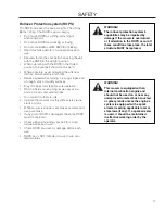
IMPORTANT INFORMATION

When control levers are in the reverse position 
they return to neutral when released. This may 
cause the mower to suddenly stop.

Steering

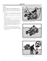
To move forward and backward

The direction and speed of the mower’s movements 
is effected by the movement of the control lever(s) 
on each side of mower. The left control lever controls 
the left wheel. The right control lever controls the right 
wheel.
first time users should push mower (see “moving 
by Hand” in the Operation section) to an open, flat 
area, without other people or vehicles/obstacles 
nearby. In order to move unit under its own power, 
the operator must be in the seat, start engine (see 
“Before Starting” in Operation section), adjust 
engine speed to idle, disengage parking brake, do 
not engage blades at this time, rotate control levers 
inward. As long as the control levers have not been 
moved forward or backwards, mower will not move. 
Slowly move both control levers forward slightly. This 
will allow mower to start moving forward in a straight 
line. Pull back on control levers to the neutral position 
and mower should stop moving. Pull back slightly on 
control levers, this will allow mower to start moving 
backwards. Push forward on control levers to the 
neutral position and mower should stop moving.

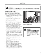
To turn to the right

While moving in a forward direction, pull the right lever 
back towards the neutral position while maintaining 
the position of the left lever, this will slow the rotation 
of the right wheel and cause the machine to turn in 
that direction.

To turn to the left

While moving in a forward direction pull the left lever 
back towards the neutral position while maintaining 
the position of the right lever, this will slow the rotation 
of the left wheel and cause the machine to turn in that 
direction.

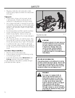
To zero turn

While moving in a forward direction, first pull both 
control levers back until the mower stops or slows 
dramatically.
Then by alternating one lever slightly to the forward 
position and the other in the reverse position. 

opeRatIon

25

Summary of Contents for 966057501

Page 1: ...Operator Manual KODIAK SE 5225 KOH CE 966057501 Original Instructions Please read the operator s manual carefully and make sure you understand the instructions before using the machine...

Page 2: ...information contained in these instructions Use only original parts for repairs The use of other parts voids the warranty Do not modify or install non standard equipment to the unit without consent fr...

Page 3: ...ng 25 Steering 25 Before Starting 26 Starting the Engine 26 Weak Battery 28 Jumper Cables 28 Running 29 Operating On Hills 30 Mowing Tips 31 Stopping the Engine 32 Manually Moving Unit 33 Maintenance...

Page 4: ...d mind and body and must not be under the influence of any mind altering substance WARNING Engine exhaust some of its constituents and certain vehicle components contain or emit chemicals known to the...

Page 5: ...ensure that the machine is well anchored DO NOT operate this machine on public roadways Towing If machine is equipped with a tow hitch use extreme caution when towing Never allow children or others i...

Page 6: ...ne s manufacturing number can be found on the printed plate affixed to the engine compartment Stated on the plate from the top are The machine s type designation I D 1 The manufacturer s type number M...

Page 7: ...marking Only for keep away from the European market discharge deck Battery acid is corrosive explosive and flammable Do not stand here Noise emissions to the surroundings in accordance with the Europe...

Page 8: ...rforming any the machine than 10 maintenance or repair work Whole body Severing of fingers Do not open or Careful backing up Careful going exposure to and toes remove safety watch for other forward wa...

Page 9: ...solutely necessary Always look down and behind before and while backing Never direct discharged material toward anyone Avoid discharging material against a wall or obstruction Material may ricochet ba...

Page 10: ...s and above are involved in a large percentage of riding mower related injuries These operators should evaluate their ability to operate the riding mower safely enough to protect themselves and others...

Page 11: ...r factor related to loss of control and tip over accidents which can result in severe injury or death Operation on all slopes requires extra caution If you cannot back up the slope or if you feel unea...

Page 12: ...l care of a responsible adult other than the operator Be alert and turn machine off if a child enters the area Before and while backing look behind and down for small children Never carry children eve...

Page 13: ...his is not possible refuel such equipment with a portable container rather than from a gasoline dispenser nozzle Keep the nozzle in contact with the rim of the fuel tank or container opening at all ti...

Page 14: ...rly Adjust and service as necessary Maintain or replace safety and instruction labels as necessary Do not modify safety equipment Check regularly to be sure it works properly The machine must not be d...

Page 15: ...igher quality mowing is desired WARNING Avoid electrical sparking and its consequences by the following routines Sparking can occur when working with the battery and the heavy cables of the starter ci...

Page 16: ...omer Responsibilities Read and observe the safety rules Follow a regular schedule in maintaining caring for and using your mower Follow the instructions under Maintenance and Storage sections of this...

Page 17: ...rmit others to ride Operate the mower smoothly without jerky turns starts or stops When mower is stopped set brakes securely and use park brake If any part of ROPS is damaged the entire ROPS must be r...

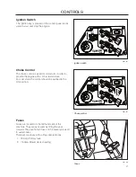
Page 18: ...cations Motion control levers 1 Parking brake 2 Throttle control 3 Blade switch 4 Ignition switch 5 Choke control 6 Fuses 7 Fuel tank cap 8 Fuel shut off valve 9 Deck lift 10 Seat adjustment lever 11...

Page 19: ...f the right wheel is reduced and the machine turns to the right Zero turn can be achieved by moving one control backward behind the neutral position and carefully moving the other steering control for...

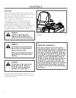
Page 20: ...rol regulates the engine speed and thereby the rate of rotation of the blades assuming the blade switch is pulled out see Engaging the Mower Deck In order to increase or decrease the engine speed the...

Page 21: ...lting the seat forward They are flat pin fuses of the same type used in automobiles There are two fuses with ratings and functions 20 Amp Primary fuse 1 7 5 Amp Mower deck coupling 2 Choke Control The...

Page 22: ...ture which leads to separation and formation of acids during storage Acidic gas can damage the fuel system of an engine while in storage To avoid engine problems the fuel system should be emptied befo...

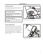
Page 23: ...low it to pivot while the lift arm rotates to the rear of the unit To stop in the desired cutting position rotate the foot pedal down into the notch in the height plate The cutting height range is fro...

Page 24: ...ch the seat can be moved backward or forward 8011 441 Lengthways adjustment Hour Meter The hour meter displays the total operating time It will flash CHG OIL Change Oil at 50 hour intervals The flash...

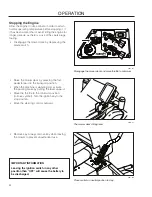
Page 25: ...ee Moving by Hand in the Operation section to an open flat area without other people or vehicles obstacles nearby In order to move unit under its own power the operator must be in the seat start engin...

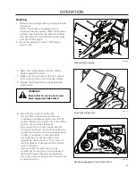
Page 26: ...rted The driver must be seated on the seat The blade switch for engaging the mower blades must be depressed The parking brake must be on Both steering controls must be in the locked outer neutral posi...

Page 27: ...should be pushed to the ON position 8061 017 Set the throttle 8061 017 Set the choke control WARNING Engine exhaust and certain vehicle components contain or emit chemicals considered to cause cancer...

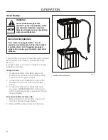
Page 28: ...RED cable to the 1 POSITIVE terminal on each battery taking care not to short against chassis Connect one end of the BLACK cable to the 2 NEGATIVE terminal of the fully charged battery Connect the ot...

Page 29: ...ously variable using the two steering controls When both controls are in the neutral position the machine stands still By moving both controls an equal amount forward or backward the machine moves in...

Page 30: ...de of the unit and engage the parking brake To restart movement release the parking brake Pull the control levers back to the center of the mower and press forward to regain forward motion Make all tu...

Page 31: ...ore even and the grass clippings more evenly distributed over the mown area The total time taken is not increased as a higher operating speed can be used without poor mowing results Avoid mowing wet l...

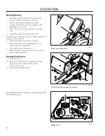
Page 32: ...depressing the blade switch 8061 017 Disengage the mower deck and move throttle to minimum Raise the mower deck by pressing the foot pedal forward to the transport position When the machine is standi...

Page 33: ...pposite the front valve below the seat support It is not visible in the illustration Use a 17 mm open end wrench or socket and ratchet Turn the outer locknut 2 3 turns Using an 8mm wrench or socket tu...

Page 34: ...Not described in this manual Refer to the engine manufacturer s manual MAINTENANCE Daily At least once each year Maintenance interval in hours Before After 50 250 500 Check the parking brake Check the...

Page 35: ...hour service 3 1 First change after 8 10 hours When operating with a heavy load or at high ambient temperatures replace every 50 hours 2 In dusty conditions cleaning and replacement are required more...

Page 36: ...12 2V 50 45 min 75 min 95 min 180 min 12 0V 25 65 min 115 min 145 min 280 min 11 8V 0 85 min 150 min 195 min 370 min Charging time depends on battery capacity condition age temperature and efficiency...

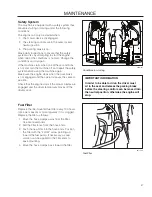
Page 37: ...ition Check that the engine stops if the mower blades are engaged and the driver temporarily moves off the drivers seat IMPORTANT INFORMATION In order to be able to drive the driver must sit in the se...

Page 38: ...tion To adjust the parking brake contact the Dixon service workshop IMPORTANT INFORMATION The machine must be absolutely standing still when applying the parking brake Tire Pressures All tires should...

Page 39: ...Clutch pulley 2 Deck belt Belt routing deck belt Deck belt installation NOTE For ease in installing the deck belt refer to the routing decal on bottom of seat Wrap the deck belt around the electric c...

Page 40: ...The belt should now be able to be removed from 3 the engine pulley and pump pulleys Belt installation Wrap the belt around the pulley 1 Route the belt around the inside of the idler pulley 2 Wrap the...

Page 41: ...tting Blades In order to attain the best mowing effect it is important that the blades are well sharpened and not damaged Bent or cracked blades or blades with large nicks should be replaced IMPORTANT...

Page 42: ...easurement Turn both outer blades to align with the 3 deck in front to rear manner Reposition rear mounting bolts up or down until rear of mower deck is positioned level to 1 8 higher in the rear than...

Page 43: ...ATION Adjust anti scalp rollers with the mower on a flat level surface The anti scalp rollers can be set in three positions Upper position 1 to 2 38 to 64 mm grass Middle position 2 to 4 64 to 102 mm...

Page 44: ...d any type of tire liner or foam fill material to the tires Excessive loads created by foam filled tires will cause premature failures Only use O E M specified tires 8050 831 Clean regularly IMPORTANT...

Page 45: ...very year 1 52 Every Week 1 365 Every day Lubricate with grease gun Oil change Filter change Lubricate with oil can Level check Change transaxles transmission filters 8050 822 Wipe away excess grease...

Page 46: ...829 Lubricating the front wheels 8011 732 Deck spindle IMPORTANT INFORMATION Use minimal lubrication and remove excess lubricant so that is does not come into contact with belts or belt pulley drive s...

Page 47: ...ese purge procedures should be implemented any time a hydrostatic system has been opened to facilitate maintenance or any additional oil has been added to the system The resulting symptoms in hydrosta...

Page 48: ...ntact of the battery terminal cable connections Blown fuse Fault in the starter safety circuit See Checking the Safety System in the Maintenance Section Engine runs rough Faulty carburetor Choke contr...

Page 49: ...ve on pump open Drive belt for the transmission slack or has come off Air trapped in hydraulic system Mower deck not engaging Drive belt for the mower deck has come loose Contact for the electromagnet...

Page 50: ...d a fuel stabilizer 4 Start the engine and allow it to run until the carburetor is drained of fuel or the stabilizer has reached the carburetor Remove the spark plug and pour about a 5 tablespoon of e...

Page 51: ...schematics 51...

Page 52: ...cluding filter 1 6 qt 1 5 liter Oil capacity including filter 1 7 qt 1 6 liter Engine oil See viscosity diagram SAE 10W30 10W40 5W20 5W30 API SF SJ Fuel Min 87 octane unleaded Max ethanol 10 Max MTBE...

Page 53: ...struction 11 gauge fabricated Productivity 4 0 acres h 16187 m2 h Dimension Weight 901 lbs 409 kg Base Machine Length 76 193 cm Base Machine Height ROPS up 74 188 cm Base Machine Height ROPS dwn 51 13...

Page 54: ...bs ft lbs Nm ft lbs Nm ft lbs Nm 9 12 13 18 5 16 18 24 28 38 24 33 3 8 31 42 46 62 40 54 7 16 50 68 75 108 75 102 115 156 9 16 110 150 165 224 5 8 150 203 225 305 250 339 370 502 7 8 378 513 591 801 1...

Page 55: ...ese labels Certificates can also be supplied with the machine at delivery or written in the Engine manual Take care of them as they are valuable documents CE Requirements The Declaration of Conformity...

Page 56: ...rake q The safety switch for the mower deck q The safety switch in the seat q The safety switch in the steering controls q Parking brake functionality q Driving forward q Driving backward q Engaging t...

Page 57: ...ired q Check the tire pressures q Check battery with cables q Lubricate according to lubrication chart q Check clean the engine s cooling air intake q Clean the air cleaner s pre filter foam q After 5...

Page 58: ...every 200 hours q Change the air filter s paper cartridge q Change hydraulic pump oil and filter 200 hours q 50 Hour Service Perform the 25 hour service q Clean replace the air cleaner s filter cartr...

Page 59: ...heck adjust the parking brake 50 hours q Clean Change the spark plugs 100 hours q Change the fuel filter 100 hours q Check the engine valve clearance q 300 Hour Service Perform the 25 hour service q P...

Page 60: ...60 Action Date mtr reading stamp sign SERVICE JOURNAL...

Page 61: ...61 Action Date mtr reading stamp sign SERVICE JOURNAL...

Page 62: ...62 Action Date mtr reading stamp sign SERVICE JOURNAL...

Page 63: ......

Page 64: ...P N 115 248226R1 01 28 10...

Reviews: