background image

8

© 2001 Directed Electronics, Inc.  

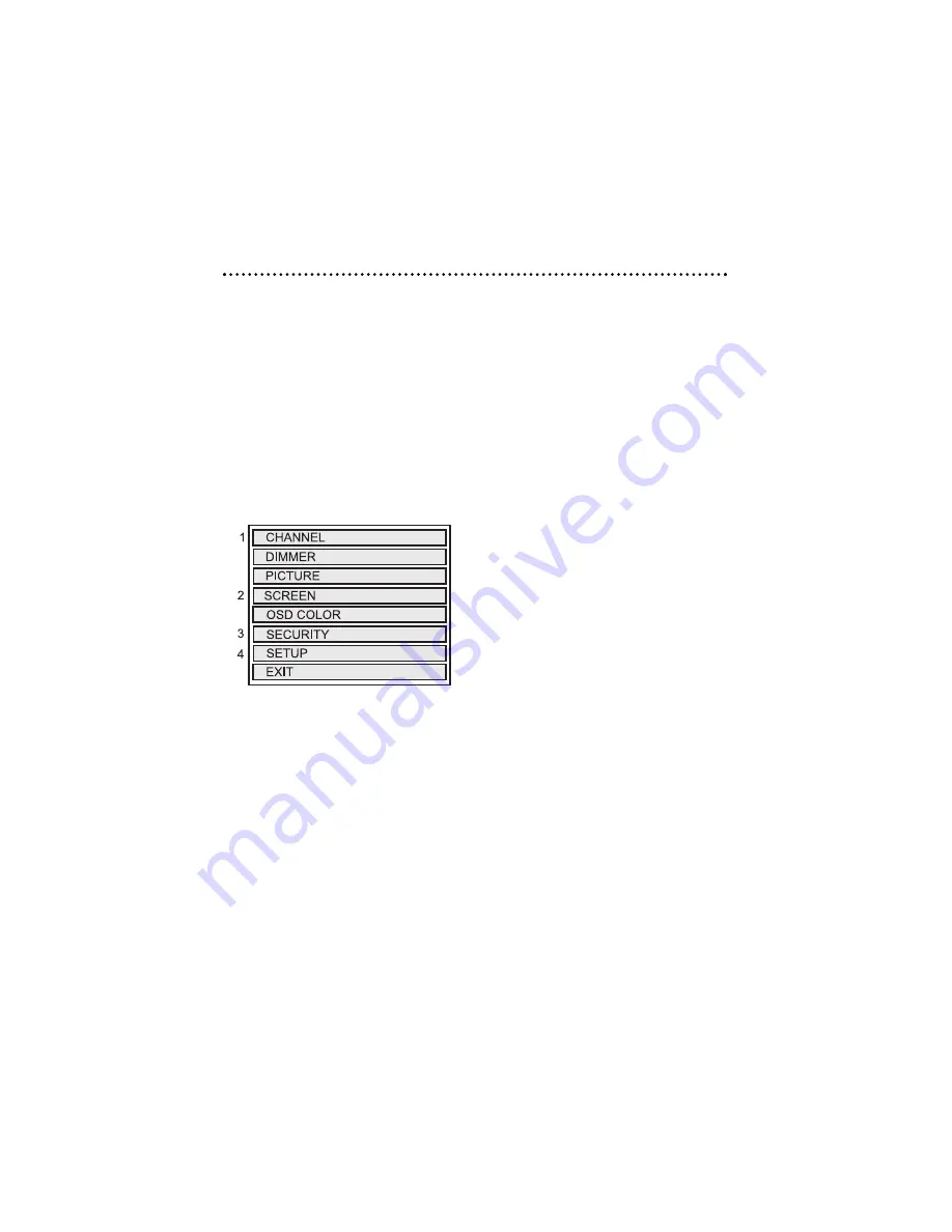
The Setup Menu is a list of programming selec-

tions that control system operation and screen

settings.

Each selection has a list of settings that can be

changed to optimize system operation. 

Some settings may have additional settings.

Notes that include any specific programming

instructions for these are included under the

selection heading.

SETUP MENU

1.

Channel

- Appears if the TVM300 is con-

nected and TV is the source.

2.

Screen

- Appears in the RVM700 monitor

menu only. 

3.

Security

- Applies when ESP/ESP2 security

systems are connected; only ESP2 will dis-
play trigger zones.

4.

Setup

- Appears if the MCB 1000 Expanded

Menu switch is on.

MAKING CHANGES TO SYSTEM
SETTINGS

USING THE MONITOR CONTROL BUTTONS

NOTE: For a guide to monitor button locations refer to

Basic Operation

section of this guide.

1.

Press 

MODE

to enter the Setup Menu. 

2.

Press 

UP

or 

DOWN

to highlight the selection.

3.

Press 

MODE

to enter that selection Menu.

4.

Press 

UP

or 

DOWN

to highlight the setting.

5.

Press 

MODE

to change the setting, display

additional settings menus, or toggle
through a list of possible settings.

USING THE UNIVERSAL REMOTE CONTROL

(Included with MCB1000)

NOTE: For a guide to remote control button locations

refer to the MCB1000 guide.

1.

Press 

MENU

to enter the Setup Menu.

2.

Press 

(+)

or 

(-)

to highlight the selection.

3.

Press 

MENU

to enter that selection menu.

4.

Press 

(+)

or 

(-)

to highlight the setting.

5.

Press 

MENU

to change the setting, display

additional setting menus, or toggle through
a list of possible settings.

EXITING MENUS

After making setting changes, use the following

steps to exit the menus.

1.

Highlight 

BACK

, press the monitor’s 

MODE

button or the remote’s 

MENU

button to

return to the previous menu

2.

Highlight 

EXIT

, press monitor’s 

MODE

button or the remote control’s 

MENU

button or make no entry for eight seconds,
you will exit all menus and return to the
current video source display.

On-Screen Menus

Summary of Contents for RVM560

Page 1: ...LCD Video Monitor MODEL RVM560 RVM680 RVM700 O W N E R S G U I D E INSTALLATION GUIDE...

Page 2: ......

Page 3: ...r Warranty 6 Features 6 Features 6 Accessories 6 Basic Operation 7 Monitor Description 7 Maintenance 7 On Screen Menus 8 Making Changes to System Settings 8 Setup Menu Descriptions and Operation 9 Sys...

Page 4: ...cover labor costs for the removal diagnosis troubleshooting or reinstallation of the unit For service on an out of warranty product a flat fate fee by model is charged Contact your authorized dealer...

Page 5: ...ECTRIC SHOCK DO NOT EXPOSE THIS EQUIPMENT TO RAIN OR MOISTURE TO REDUCE THE RISK OF FIRE OR ELECTRIC SHOCK AND ANNOYING INTERFERENCE USE ONLY THE INCLUDED HARDWARE THIS MONITOR IS ONLY DESIGNED FOR RE...

Page 6: ...pli ance could void the user s authority to operate this device YOUR WARRANTY Your warranty registration must be completely filled out and returned within 10 days of pur chase Your product warranty wi...

Page 7: ...nnel up and down when TVM300 module is connected 5 Mode button Changes up down buttons functions 6 LED indicator light When turned on the light is blue when on standby the light is red MAINTENANCE Kee...

Page 8: ...Menu 2 Press UP or DOWN to highlight the selection 3 Press MODE to enter that selection Menu 4 Press UP or DOWN to highlight the setting 5 Press MODE to change the setting display additional settings...

Page 9: ...s CONTRAST Adjusts picture contrast buttons HUE Adjusts picture hue NTSC only SCREEN RVM700 ONLY WIDESCREEN 16 9 Wide screen videos will appear undistorted and fit the full screen Normal videos 4 3 wi...

Page 10: ...re Before the menu is exited the write to system procedure must be completed SYSTEM SETTINGS MENU SELECTION DESCRIPTION AND OPERATION PASSIVE ACTIVE ARMING Program the ESP ESP2 security system to arm...

Page 11: ...urn to the power on off state it was in when the key was turned off FM MODULATOR Select to let the MCB1000 know an FM modulator is connected FM MODULATOR allows the universal remote to turn the FM mod...

Page 12: ...enter the system changes WRITING TO SYSTEM will be displayed WRITE SUCCESSFUL Information entered successfully WRITE FAILED Information not entered successfully ASSIGN TRIGGER NAMES MENU NOTE In this...

Page 13: ...ENSOR ZONE X MOTION TILT SENSOR ZONE X GLASS BREAK SENSOR ZONE X SHOCK SENSOR 2 ZONE 8 Select to change the name of zone 8 from the zone names list at the end of this section WRITE TO SYSTEM Highlight...

Page 14: ...TOR All monitors that work with the OHC100 attach to the monitor door in the same way Start with the monitor door in the viewing position At both bottom corners of the monitor are spring loaded monito...

Page 15: ...15 2001 Directed Electronics Inc Monitor Connector Monitor Mounts...

Page 16: ...curity car stereo products rear seat entertainment and accessories available The recipient of more than 20 patents in the field of advanced electronic technology Directed is ISO 9001 registered Qualit...

Reviews: