


Fig.4
Fig. 5a
Fig.6
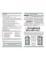
Step 3: Unpacking Carton 3 of 3
and assemble Top & Base Assembly to rack.
Installing the Top with dual fans and Base Assemblies, Casters, Legs,
and Base Cable Plates
(as needed)
to rack assembly.
Using six
(6)
M5x10 screws
(F)
attach
the Top Assembly with dual fans
(4)
as
unpacked from carton 1 of 3 and attach
to Rack Assembly as shown in Figure 4.
Using four
(4)
M5x10 screws
(F)
attach
the Base Assembly
(5)
as unpacked
from carton 1 of 3 and attach to Rack
Assembly as shown in Figure 4.
Using six
(6)
M5x10 screws
(F)
(six per
caster)
attach two
(2)
Locking Casters
(D)
onto the bottom Front Assembly
(1)
and two
(2)
Standard Casters
(D)
onto
the bottom Back Assembly
(2)
as
shown in Figure 5a.
Using a wrench attach two
(2)
of the
Adjustable Locking Feet
(C)
onto the
bottom Front Assembly
(1)
the
bottom Back Assembly
(2)
as shown
in Figure 5a.
Installing the four (4)
(as needed)
Base Cable Plates
(E)
to the Rack Assemblies
C
AUTION
:
Do to the height and weights of the Professional Series Racks do not move and/or stand up by yourself
assistance is required. Always use an assistant or mechanical lifting equipment to safely lift and position equipment.
Stand up the completed rack assemblies. Using two
(2)
M5x10 screws
(F)
for
each of the
(as needed)
Base Cable Plates
(E)
(Fig.5b) attach each to the top
side of Base Assembly
(5)
as shown in Figure 5a.
Step 4:
Attaching the doors and panels to the
Rack Assemblies
Attach the Custom Tempered Glass Door
(1)
,
the Vented
Back Door
(2)
,
and the left & right Side Panels
(3)
to the
completed rack assemblies as shown in Figure 6.
Installing & Adjusting the Front (1) & Back (2) Doors.
1) The Front Door
(1)
and the Back Door
(2)
are removable at
any time. Just pull down on the top tap while holding the door.
The top of the door will then fall out of place, then pull up on
the bottom tab and lift the door out of the frame.
2) There may be times when the door may need to open to the
other directions. The door’s opening direction can be changed.
Remove the door and turn it so that the handle is on the other
side. Insert the tabs into the holes and close the door.
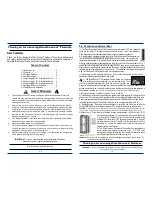
.
1.0
H
ARDWARE
L
IST
:
Actual parts appearance and quantity may differ from illustration.
ID Quantity
Description
ID Quantity
Description
1
1
Front Assembly
A
1
Left Threaded Mounting Rail
2
1
Back Assembly
B
1
Right Threaded Mounting Rail
3
2
Side Assembly
C
4
Adjustable Locking Feet
4
1
Fan Top Assembly
D
4
Heavy Duty Casters
(2- standard / 2 - locking)
5
1
Base Assembly
E
4
Base Cable Plates
6
1
1U Power Strip
F
42
M5x10mm bolt
(assembly)
7
1
1U Thermal Control G
42
M6x12mm bolt
(assembly)
8
1
Power Cord
(Thermal)
H
38
10-32 bolt
(mounting rails)
9
4
Keys
I
38
10-32 nut
(mounting rails)
10
1
Manual
J
1
Left Knockout Mounting Rail
K
1
Right Knockout Mounting Rail
3 / 8
6 / 8
Fig.5b