2
Introduction
2
Description
2
Technical data
2
Usage limits (IEC 60974-1)
2
Installation
3
Usage norms
3
Electrical wiring of the welding cooling device and
successive mechanical coupling
3
Start-up / drainage
4
Maintenance
4
Wiring diagram
5
Hydraulic diagram
5
Meaning of graphic symbols on machine
5
Introduction
Thank you for choosing one of our products. In order to obtain
maximum performance from the cooling module and to ensure its
parts maximum life, the operating and maintenance instructions
and the safety instructions contained in a separate booklet must be
read carefully and strictly followed. If the cooling module requires
repair, we recommend our customers to contact the workshops of
our customer service, who have suitable tooling and highly quali-
fied and trained technical staff. All our cooling modules and devi-
ces are subject to continuous development, so we must reserve
the right to make changes to their manufacture and equipment.
Description
•
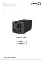
The cooling module is designed for the air circulation of welding
torches. It is used for particularly difficult welding operations and
consists mainly of:
•
A single-phase electric pump.
•
A plastic tank.
•
A cooler.
•
A pressure monitor.
•
A fuse.
The cooling module is particularly compact and lightweight. It
is designed as part of a welding power source. For other appli-
cations, please contact your DINSE consultant.
Technical data
The general technical data of the cooling module are summa-
rized in table 1.
Table 1
Model
DIX CM 141.M DIX CM 592.M
Single-phase input
V
230
400
Frequency
Hz
50/60
50/60
Max power supply
kW
0,3
0,3
Max current absorbed
A
1,35
0,9
Delayed fuse
A
2
1,6
Coolant
DIX CM Liquid 10
Cooling power Φ
1
@ 1 l/min
@ 1,6 l/min (with TIG torch)
kW
kW
0,5
0,65
0,5
0,65
Capacity with 4 m TIG torch
l/min
1,6
1,6
Max pressure
bar
4,3
4,3
Protection class
IP 23
IP 23
Insulation class
F
F
Tank capacity
l
2,5
2,5
Dimensions
mm
515-225-185
545-225-185
Weight
kg
9,5
10
Weight with liquid
kg
12
12,5
Copyright © 2018 DINSE G.m.b.H., Hamburg.
These instructions or excerpts there of shall not be duplicated, transla-
ted or reproduced, nor shall they be stored, processed, transmitted or
distributed by any electronic means without the prior written permission
of DINSE G.m.b.H.
D I N S E G . m . b . H .
Tarpen 36 • D-22419 Hamburg
Tel. +49 (0)40 658 75-0
Fax +49 (0)40 658 75-200
[email protected] – www.dinse.eu


