Dimplex VCX1525 Owner'S Manual Download Page 11


11


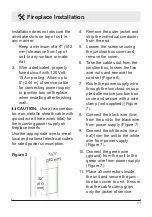
Fireplace Installation 

installation does not obscure the 

air intake slots on top of unit in 

any manner.

Keep a minimum of a 4" (102 

mm) clearance from top of 

unit to any surface or mate-

rial.

3.  Wire a dedicated, properly 

fused circuit with 120 Volt, 

15 Amp rating.  Allow up to 

8' (2.44 m) of service cable 

for connecting power supply 

to junction box on fireplace 

when installing after finishing 

wall.


CAUTION:  

Use a two conduc-

tor, non-metallic sheath cable with 

ground wire (three wires total) for 

the incoming power supply on 

fireplace inserts. 
Use the appropriate wire to meet 

local and national electrical codes 

for rated power consumption.

4.  Remove the outer jacket and 

strip the individual conductor 

from the end.

5.  Loosen the screw securing 

the junction box cover and 

remove the cover.

6.  Take the cables out from the 

junction box, loosen the two 

wire nuts and remove the 

cord set (Figure 6).

7.  Route the power supply wire 

through the knockout on sup-

plied alternative junction box 

cover and secure with a wire 

clamp (not supplied) (Figure 

7).

8.  Connect the black wire (live) 

from the unit to the black wire 

from power supply (Figure 7).

9.  Connect the white wire (neu-

tral) from the unit to the white 

wire from power supply  

(Figure 7).

10. Connect the green wire 

(ground) from the unit to the 

green wire from power supply 

(Figure 7).

11.  Place all connectors inside 

the unit and secure the junc-

tion box cover to unit.  Ensure 

that the cable clamp grips 

only the jacket of service 

Figure 5

32"

(813 

mm)

14¼"

(362 mm)

Summary of Contents for VCX1525

Page 1: ...visit www dimplex com 7209350100R07 IMPORTANT SAFETY INFORMATION Always read this manual first before attempting to install or use this fireplace For your safety always comply with all warnings and sa...

Page 2: ...emphasize CAUTION Procedures and techniques which if not carefully followed will result in damage to the equipment WARNING Procedures and techniques which if not carefully followed will expose the us...

Page 3: ...uct Under Manufacturer s Warranty Contact us at www dimplex com customer_support For Troubleshooting and Technical Support OR Toll Free 1 888 DIMPLEX 1 888 346 7539 Monday to Friday 8 00 a m to 4 30 p...

Page 4: ...nctions Disconnect power at the service panel and have the heater inspected by a reputable electrician before reus IMPORTANT INSTRUCTIONS ing Do not operate any unit with a damaged cord or plug or if...

Page 5: ...fit contact a qualified electrician to install the proper outlet Always plug heaters directly into a wall outlet receptacle Never use with an extension cord or relocatable power tap outlet power strip...

Page 6: ...residential installation This equipment generates uses and can radiate radio frequency energy and if not installed and used in accordance with the instructions may cause harmful interference to radio...

Page 7: ...circuit will be required if after installa tion the circuit breaker trips or the fuse blows on a regular basis when the heater is operating Ad ditional appliances on the same circuit may exceed the cu...

Page 8: ...face such as a ta bletop to ensure adequate space for heat exhaust from the bottom of the fireplace Figure 3 3 With a wall stud finder locate the center of the wall stud drive a wood screw into the st...

Page 9: ...for mounting the fire place 7 With the glass assembly tak en off mount the firebox onto the two mounting screws 8 Mark position of hole H 9 Remove fireplace from wall 10 Install drywall anchor into dr...

Page 10: ...allation including the thickness of dry wall is required Make sure there is enough clearance for the cable coming out from the bottom of the fireplace NOTE Where there are close tolerances involved in...

Page 11: ...ove the outer jacket and strip the individual conductor from the end 5 Loosen the screw securing the junction box cover and remove the cover 6 Take the cables out from the junction box loosen the two...

Page 12: ...in Figure 4 Bathroom Installation This firebox must be protected by a GFI receptacle or circuit for bathroom use If receptacle is used it must be readily acces sible This unit is an electrical applia...

Page 13: ...n Add wood screws here Figure 8 Figure 9 Top Bracket Bottom Bracket WIRING M M ELEMENTS THERMOSTAT 3 POSITION SWITCH N L CUTOUT HEAT SWITCH FLICKER MOTOR LOWER LIGHTS BLOWER MOTOR INTEGRAL ON OFF R C...

Page 14: ...the unit is off B Heater On Off Switch The Heater On Off Switch sup plies power to the heater fan and the heater element When the switch is in the ON po sition the heater operates if the thermostat ca...

Page 15: ...h an integrated on off remote control NOTE Ensure that the fire place 3 Position Switch is set to the remote control setting To operate push the ON button to turn fireplace on push the OFF button to t...

Page 16: ...ints It is a good idea to replace all light bulbs at once if they are close to the end of their rated life Group replacement will reduce the number of times you will need to open the unit to re place...

Page 17: ...usting lightly with a clean dry cloth To remove fingerprints or other marks the glass can be cleaned with a damp cloth The glass should be completely dried with a lint free cloth to prevent water spot...

Page 18: ...imited warranty have been tested and inspected prior to shipment and subject to the provisions of this warranty Dimplex warrants such products to be free from defects in material and workmanship for a...

Page 19: ...sponsible for IN NO EVENT WILL DIMPLEX OR ITS DIRECTORS OFFICERS OR AGENTS BE LIABLE TO THE PURCHASER OR ANY THIRD PARTY WHETHER IN CON TRACT IN TORT OR ON ANY OTHER BASIS FOR ANY INDIRECT SPECIAL PUN...

Page 20: ...Mirror 5901180100RP Thermostat 2300150100RP Heater On Off Switch 2800070700RP Thermostat Control Knob 8801080100RP 3 Position Switch 2800071100RP Remote Control Receiver 3000380200RP Heater Assembly...

Reviews: