background image

Technical manual 


Page 51 of 72 

ST0133 – A 02/09 


SOLAR 

6.5 Pipe work fixation 

When fixing the pipe work to the building structure a number of points should be con-
sidered before choosing the fixation method: 
- temperature of liquid carried in pipes 
- sound transfer from pipe work into building structure 
- thermal expansion and contraction of pipe work due to large temperature changes 
- safe securing of pipe work to building structure 
- fire safety 
 
It  is  important  that  the  pipe  work  is  secured to the building structure in a safe and 
proper manner. Only wall/floor fixings that are suitable for the given conditions should 
be used. When routing the pipe work on the outside of the building also the aesthetic 
impact of the pipe work on the building should be considered. 
 
The recommended distance between fixation points for various copper pipe sizes are 
shown in Figure 54. 


Figure 54 – Distance between fixation points of copper pipe work 

6.6 Pipe work insulation 

Additional requirements are in place for insulation used in solar thermal installations 
compared with conventional heating and hot water systems. When choosing a suitable 
insulation the following should be considered: 
- the heat transfer medium in the pipe work can reach +150°C 
- the insulation has to be UV and weather resistant 
- the insulation should be at least 100% of the inner pipe diameter (e.g. a 22mm pipe 

should be insulated with at least 19mm of insulation). 

 
The Dimplex solar connection hoses which are delivered with the various roof fixing kits 
and the 10m and 15m flexible pipes SOLFH10/15 are insulated with the appropriate 
material. 

Summary of Contents for Solar Series

Page 1: ...Page 1 of 72 ST0133 A 02 09 SOLAR Technical Manual Complete guide to Dimplex Solar ...

Page 2: ...LAR CONTROL UNIT SOLCU1 2 3 24 4 2 1 General description 24 4 2 2 Temperature sensors 25 4 2 3 Technical data 26 4 3 DIMPLEX SOLAR PUMP UNIT SOLPU1 2 26 4 3 1 General description 26 4 3 2 Pump connection 30 4 3 3 Technical data 31 4 4 DIMPLEX SOLAR EXPANSION VESSELS SOLEV 32 4 4 1 General description 32 4 4 2 Expansion vessel sizing 32 4 4 3 Technical data 35 4 5 DIMPLEX EXPANSION VESSEL FIXING KI...

Page 3: ...URE DROP 50 6 4 PIPE WORK LIQUID CONTENT 50 6 5 PIPE WORK FIXATION 51 6 6 PIPE WORK INSULATION 51 7 COMMISSIONING 52 8 OPERATION 53 8 1 CONTROL UNIT 53 8 2 PUMP UNIT 55 9 MAINTENANCE 55 10 PRODUCT AND KIT LISTINGS 58 10 1 DIMPLEX SOLAR KITS 58 10 2 DIMPLEX SOLAR COMPONENTS 58 11 DIMPLEX LITERATURE STRUCTURE 60 12 APPENDIX 61 12 1 ON SITE QUESTIONNAIRE 61 12 2 ON SITE INSPECTION 62 12 3 DIMPLEX SOL...

Page 4: ...do not hesitate to contact us 3 Solar thermal 3 1 Introduction The sun supplies every day a multiple of the required world wide daily energy demand to the earth The energy of the sun is available in various forms such as direct diffuse and reflected solar radiation wind waves the ground and in other forms Solar thermal systems convert the energy incident from the sun on an absorber surface into se...

Page 5: ...tside the earth s atmosphere the so called extraterres trial radiation has a density of 1367 W m Depending on the location of the solar system the time of day and year the obstacles in the atmosphere such as cloud cover and pollution and the inclination of the solar system in relation to the sun this value varies strongly A map of the United Kingdom and Ireland is shown in Figure 3 indicating aver...

Page 6: ...r the incident radiation onto the collector surface can vary although it might be in the same location The terminology used to describe the exact location and orientation of a solar collector is described in Figure 4 The terms indicate longitude geographic coordinate for East West measurement latitude geographic coordinate North or South of the equator slope angle between the horizontal and the co...

Page 7: ...7 of 72 ST0133 A 02 09 SOLAR Figure 4 Terminology to describe location and orientation of solar thermal panel Figure 5 Effect of orientation on incident radiation levels Latitude Longitude S W N E Zenith Slope Azimuth S U N ...

Page 8: ...a solar thermal system Although solar thermal systems cover a whole range of applications see Figure 1 the basic components used are in principle the same A solar thermal system consists of solar collector heat transfer medium pipe work pump and safety equipment heat exchanger storage facility control unit user Applying the above to a domestic hot water system the individual components are identif...

Page 9: ...and the connection point for the expansion vessel Heat exchanger The heat exchanger allows a hydraulic separation of systems but allows the transfer of energy between the two systems i e the solar circuit and the wholesome water In a domestic solar thermal hot water system the heat exchanger is usually in form of a coil immersed in the wholesome water inside the hot water cylinder To ensure the so...

Page 10: ...rol unit switches the pump either on or off depending on the temperature difference between T1 and T2 and the temperature reached in the storage device The location of the tempera ture sensors is indicated in Figure 7 Figure 7 Location of temperature sensors in solar thermal system If T1 is greater than T2 plus an additional temperature differential called ΔT delta T the circulation pump is being ...

Page 11: ...220 is given in Figure 8 detailing the individual col lector components Figure 8 Flat plate collector components Due to its construction a flat plate collector is subject to conduction convection and radiation heat losses The sum of these heat losses and the design and production qual ity are summarised in the thermal collector efficiency which is empirically determined through independent third p...

Page 12: ...dent radiation tm C collector middle temperature ta C collector ambient temperature Figure 9 SOLC220 heat loss modes The collector heat loss front 7 and collector heat loss back 8 are dependant on the operating conditions of the solar thermal collector i e primarily on the temperature difference between the collector module and the ambient air and wind speed Applying equation 1 to the Dimplex SOLC...

Page 13: ...igned for the application offering all the re quired features such as collector orientation storage heating operating temperatures heating demand and others Beside the thermal efficiency of the solar collector various other parameters are of im portance for the correct application thereof All of these parameters are determined in accordance with EN12975 and some of them are detailed in Figure 25 T...

Page 14: ...ne collector for small or large installations left hand or right hand side connection of single collector installations up to 10 collectors directly connected together collectors connected in parallel to each other thus low overall pressure drop of array same collector for vertical or horizontal installations The sensor pockets to connect the collector sensor T1 from the control unit are always on...

Page 15: ...anked off using the blanking pieces 9 2 The connections components are depicted in Figure 12 using the same references as in the installation manuals Figure 12 Connection components Dimplex SOLC220 collector An overall view of the application of the individual connection components is given in Figure 13 two collectors flow left hand side return right hand side Note the sensor pockets on both colle...

Page 16: ...g also the pressure drop at nominal low flow and high flow flow rates Figure 14 Collector connection options flow rates and pressure drop 2 3 4 5 6 7 No of collectors 1 8 9 10 Flow rate l min Pres drop mbar 1 2 150 325 2 4 150 330 3 6 150 330 4 8 160 340 5 10 160 340 6 12 170 350 7 14 185 385 8 16 195 400 9 18 200 420 210 500 10 20 ...

Page 17: ... Figure 14 and the sensor placed in the sensor pocket on the collector flow 4 1 3 Roof fixing kits The Dimplex solar collectors SOLC220 can be installed in most situations on or near a building An overall view of the installation options is shown in Figure 15 Figure 15 Dimplex Solar collector installation options Dimplex offers a wide range of roof fixing kits for the installation of the SOLC220 s...

Page 18: ...ign of the bracket fixation of the collector support rail to the roof structure In roof kits The in roof kits are only available for vertical collector installation and vary for tile roof coverings and slate covering only Additional flashing kits are available to complement the integrated roof kits covering the pipe work on the side of the collector the fixing brackets at the bottom and the gap be...

Page 19: ...on uneven ground or for suspended installation When more than one row of solar collectors is being installed it is important to minimise the impact of shading of one row to the other Equation 2 can be used to calculate the optimum row spacing to avoid shading at solar noon on the least favourable day of the year i e 21st December s s mm c p α α β sin 180 sin 1870 _ 2 Where p_c mm pitch between col...

Page 20: ... this is not always practicable especially when the roof surface must not be penetrated for water tight ness reasons Equation 4 is to be used to calculated the required mass to securely locate the free standing kit The required parameters can be found in Figure 20 Note the stated parameters are only valid for the wind speeds stated in Figure 20 It is the responsibility of the installer mechanical ...

Page 21: ...kg mass of collector SOLC220 34 5 kg Figure 20 Free standing kit support weight calculation details In some cases it might be required to prepare the load baring structure in advance to accept the fittings of the Dimplex solar free standing kit Figure 21 details the support feet 4x for each collector and the free standing bottom bar 2x for each collector Figure 21 Fixation details Dimplex solar fr...

Page 22: ... free standing mounting kits do not in clude the space required to fit the connection pipes as these vary depending on the pipe feed through chosen The dimensions provided for the integrated roof kits include the pipe work as the pipe feed through is part of the integrated roof kit Figure 22 Space requirement Dimplex SOLC220 on roof installation Figure 23 Space requirement Dimplex SOLC200 in roof ...

Page 23: ...Technical manual Page 23 of 72 ST0133 A 02 09 SOLAR Figure 24 Space requirement Dimplex SOLC220 free standing installation ...

Page 24: ...ntrol units with differing input and output options and functionality All control units operate on the basic principles described in chapter 3 3 2 Figure 26 shows the SOLCU1 control unit detailing the main components which are common to all Dimplex solar control units Figure 26 Dimplex solar control unit overall view SOLCU1 Operating switch ON AUTO Ø OFF LCD display animated backlit controller ope...

Page 25: ... sensors x2 3 0m When extending the collector sensor the overvoltage protection box is to be used to protect the control unit from voltage surges caused by lightening see Figure 27 The overvoltage protection box is part of the pump unit delivery The cable used for the extension of any of the sensors should meet the following mini mum requirements 0 75mm up to 50m long 1 50mm up to 100m long Note S...

Page 26: ...ll view Dimplex solar control units SOLCU1 2 3 4 3 Dimplex solar pump unit SOLPU1 2 4 3 1 General description The Dimplex solar pump units SOLPU1 and SOLPU2 comprise a number of features aid ing in the installation commissioning operation and maintenance of the solar thermal installation The components of the pump unit are depicted in Figure 29 followed by a brief description of their function ...

Page 27: ...lat seal is part of the delivery of the Dimplex solar flexible hose SOLFH10 15 The F x 22mm straight connection has to be provided by the installer The SOLPU2 pump unit connections follow the same principle as those of the SOLPU1 except that the connection diameters are increased 1 flat seal at the end of corrugated stainless steel pipe 1 F x 22mm or 1 F x 28mm straight connection 22mm reducing se...

Page 28: ...ll operating conditions Non return ball valve temperature gauge 5 and 16 The non return valve is critical in a solar thermal system to avoid gravity circulation at times when the cylinder is warmer than the collector as during night time hours The non return valves avoid unwanted gravity circulation from the cylinder to the collector thus losing energy from the system As both the flow and the retu...

Page 29: ...ar loop It aids during the commission ing process to adjust the flow rate correctly and assists during operation maintenance and troubleshooting to identify eventual problems Air purger and related components 11 14 and 15 The heat transfer medium used has a high affinity to air thus the air does not readily separate from the medium while the medium is cold At the beginning of the operation of a so...

Page 30: ...nto the control unit as shown in the control unit manual When using an unvented hot water system the pump has to be wired through the twin thermostat at the cylinder Figure 31 shows the wiring schematic utilising the 4 way wiring centre provided with the pump unit Figure 31 Wiring of solar circulation pump to control unit utilising 4 way wiring centre The use of a motorised two port valve is not r...

Page 31: ...ST0133 A 02 09 SOLAR Should the above conditions not be given the motorised two port valve has to be in stalled in series to the twin thermostat 4 3 3 Technical data Figure 32 Technical data Dimplex solar pump unit SOLPU1 and SOLPU2 ...

Page 32: ...4 2 Expansion vessel sizing A number of parameters have to be considered when sizing the expansion vessel The parameters to be considered are total system volume static height of system expansion coefficient of heat transfer medium opening pressure of pressure relief valve required pressure in highest system point number of collectors installed fluid content of each collector Applying the above sy...

Page 33: ...ill pressure ppc of the system The cold fill pressure ppc depends on the static height hstat of the solar thermal system and the required pressure in the highest system point pmin The defini tion of the static height hstat is depicted in Figure 33 Figure 33 Definition of static height of solar system The pressure in the highest system point pmin should be between 1 and 1 5 bar The cold fill pressu...

Page 34: ...adjusted before the system is being filled and pressurised Once the theoretical expansion vessel volume has been calculated the next larger available vessel is to be chosen A sizing guide of the expansion vessel under the stated conditions is given in Figure 34 Please note that the calculation should be carried out in the case that the assumptions shown in Figure 34 do not apply Figure 34 Expansio...

Page 35: ...tion The expansion vessel fixing kit SOLVK1 aids with the installation maintenance and de commissioning of the solar thermal system The product consists of see Figure 36 expansion vessel wall bracket suitable for vessels of up to 440mm 500mm corrugated stainless steel hose with flat seal connections quick fit connection Figure 36 Components Dimplex solar expansion vessel fixing kit SOLVK1 01 02 03...

Page 36: ...ing can be used to reconnect the vessel to the system 4 5 2 Technical data Figure 37 Technical data Dimplex expansion vessel fixing kit SOLVK1 4 6 Dimplex heat transfer medium SOLHT20 4 6 1 General description The Dimplex solar heat transfer medium SOLHT20 is a ready to use 1 2 polypropylene glycol fluid for solar thermal installations The product has particularly good characteris tics at higher t...

Page 37: ...pipe routing of the cylinders is in such a way that during water draw offs the stratification of the stored hot water is effected as little as possible ensuring the maximum amount possible to be drawn at high water temperatures In addition the sloped outlet pipe of the cylinder minimises the required installation height and reduces the heat losses from the unit to a minimum The corrugated stainles...

Page 38: ... ST0133 A 02 09 SOLAR Figure 39 Overall view Dimplex solar SCx unvented stainless steel cylinders SCx175 215 255 305sd SCx175 215 255 305si 18 01 02 03 04 05 07 08 09 10 11 12 13 14 15 16 17 18 01 02 03 04 05 07 12 13 14 15 16 17 06 ...

Page 39: ...se illustrations do not show all the required components to ensure a safe and reliable operation of the systems Figure 41 shows the integration using 2x two port motorised valves The advantage of this system is that the provision of space heating and the provision of domestic hot wa ter can be carried out independently Figure 42 shows the application of a three way diverter valve allowing the prov...

Page 40: ...Technical manual Page 40 of 72 ST0133 A 02 09 SOLAR Figure 41 Auxiliary loop integration 2x motorised two port valve ...

Page 41: ...Technical manual Page 41 of 72 ST0133 A 02 09 SOLAR Figure 42 Auxiliary loop integration 1x motorised two port valve and mid position valve ...

Page 42: ...pment as part of the scope of delivery each cylinder must have its own save discharge in accordance with building regula tions connect the cylinders on the potable and energy supply side in series when an even demand is required over a period of time connect the cylinders on the potable and energy supply side in parallel when peak demands are expected exceeding the capacity of an individual cylind...

Page 43: ...Technical manual Page 43 of 72 ST0133 A 02 09 SOLAR 4 7 4 Technical data Figure 44 Technical data Dimplex solar cylinder SCx A L K M D N E F O J B C P I G H ...

Page 44: ...lex solar SCx cylinder coils 4 8 Dimplex solar accessories 4 8 1 General description To aid in the installation commissioning maintenance and the realisation of more com plex systems Dimplex offer a range of accessories as summarised in Figure 46 Figure 46 Dimplex solar accessories ...

Page 45: ...ngs from the collector to the pump unit and from the pump unit to the cylinder 10m or 15m length The SOLFH10 15 pipe work reduces the installation time considerably by reducing the number of joints to be performed insulation of the pipe work separately laying the sensor cable and ensuring the leak tightness along its installation The technical data of the SOLFH10 15 pipe work is summarised in Figu...

Page 46: ...of covering SOLFTM sheet metal roof covering plain or corrugated For each pipe feed through one tile of the appropriate type is required The product allows pipes and cables from 0 to 35mm to be fed securely into the roof The feed through tiles are suitable for plain copper tubing and for corrugated stainless steel hose An overall view of the two types of feed through tiles and the technical data a...

Page 47: ...mulation software to allow reliable solar fraction predictions The informa tion required to reliably specify a domestic solar thermal hot water system is shown in Figure 49 Figure 49 Required information for domestic solar thermal hot water system sizing It can be seen from Figure 49 that the suitability of solar thermal depends primarily on the user and the local conditions 5 2 Sizing guide ...

Page 48: ...Technical manual Page 48 of 72 ST0133 A 02 09 SOLAR Figure 50 Dimplex solar initial sizing guide ...

Page 49: ...m Due to its ease of use and the readily available fittings it is recommended to use copper as pipe material Steel pipe work can also be used when it is ensured that it always terminates into a brass fitting before getting in contact with copper The joints of the pipe work must be carried out in such a way that they are suitable for the pressure and the temperatures present in the solar thermal sy...

Page 50: ...pproximate pressure drop Δp_pipe in 1m of pipe work at 0 5 and 0 7m s assuming that the glycol pressure drop is 30 higher than that of water Figure 52 Pressure drop copper pipe per metre 6 4 Pipe work liquid content To be able to reliably determine the liquid content of the system when specifying the required amount of heat transfer medium and when sizing the expansion vessel Figure 53 summarises ...

Page 51: ...hetic impact of the pipe work on the building should be considered The recommended distance between fixation points for various copper pipe sizes are shown in Figure 54 Figure 54 Distance between fixation points of copper pipe work 6 6 Pipe work insulation Additional requirements are in place for insulation used in solar thermal installations compared with conventional heating and hot water system...

Page 52: ...al manual Page 52 of 72 ST0133 A 02 09 SOLAR 7 Commissioning The commissioning of a Dimplex solar thermal system is a simple procedure as outlined in Figure 55 Figure 55 Dimplex commissioning procedure Part 1 ...

Page 53: ...is fully automatic and does not require any user intervention to ensure its efficient safe and reliable operation However the solar control unit offers a number of useful information that might be of interest to the user In addition the following settings and functions can be altered and activated or deacti vated as applicable see Figure 56 cylinder temperature setting temperature unit F C ...

Page 54: ...Technical manual Page 54 of 72 ST0133 A 02 09 SOLAR holiday and frost protection function variable speed control of circulating pump Figure 56 Display information and menu structure SOLCU1 ...

Page 55: ...nted hot water installation Figure 58 details the schedule of the maintenance to be carried out It is recommended to check the function of the system after the 1st year of operation and then carry out a bi annual maintenance check Not all steps have to be undertaken every two years as detailed in Figure 58 All the values measured during the mainte nance procedure are to be recorded in the appropri...

Page 56: ...member to return the control unit into AUTO when testing is complete Check sensor readings The sensor readings can be checked in the display of the control unit by pressing the up and down buttons Should any doubt exist about the correct reading the sensor should be exchanged against another sensor in the system for reference and replaced if re quired Check frost protection and pH value of heat tr...

Page 57: ...Technical manual Page 57 of 72 ST0133 A 02 09 SOLAR Figure 58 Overall view Dimplex solar maintenance procedure ...

Page 58: ...hermore the kits are structured to allow a 1st fix and 2nd fix installa tion should the installation be done in stages such as in new build situations The cylinders are to be ordered separately as they differ in type direct and indirect auxiliary heating and the size of cylinder relative to the collector area can vary The kits are summarised in Figure 59 the cylinders are listed in Figure 60 along...

Page 59: ...Technical manual Page 59 of 72 ST0133 A 02 09 SOLAR Figure 60 Dimplex solar components overall view ...

Page 60: ...ses the available documents and their rele vance at the various stages of the product s application Figure 61 Dimplex solar literature structure Planning sizing and system design Product implementation stage Operation and trou bleshooting Installation commis sioning and mainte nance Technical Manual On Site Guide Installation manuals Collector and roof kit man ual Control unit manual Pump unit man...

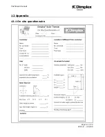
Page 61: ...Technical manual Page 61 of 72 ST0133 A 02 09 SOLAR 12 Appendix 12 1 On site questionnaire ...

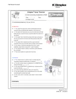
Page 62: ...Technical manual Page 62 of 72 ST0133 A 02 09 SOLAR 12 2 On site inspection ...

Page 63: ...Technical manual Page 63 of 72 ST0133 A 02 09 SOLAR ...

Page 64: ...Technical manual Page 64 of 72 ST0133 A 02 09 SOLAR ...

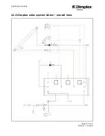
Page 65: ...Technical manual Page 65 of 72 ST0133 A 02 09 SOLAR 12 3 Dimplex solar system direct overall view ...

Page 66: ...Technical manual Page 66 of 72 ST0133 A 02 09 SOLAR 12 4 Dimplex solar system indirect overall view ...

Page 67: ...Technical manual Page 67 of 72 ST0133 A 02 09 SOLAR 12 5 Example Dimplex solar simulation report ...

Page 68: ...Technical manual Page 68 of 72 ST0133 A 02 09 SOLAR ...

Page 69: ...Technical manual Page 69 of 72 ST0133 A 02 09 SOLAR ...

Page 70: ...Technical manual Page 70 of 72 ST0133 A 02 09 SOLAR ...

Page 71: ...Technical manual Page 71 of 72 ST0133 A 02 09 SOLAR ...

Page 72: ...Technical manual Page 72 of 72 ST0133 A 02 09 SOLAR 13 Notes and sketches ...

Reviews: