Dimplex OS2527GB Service Manual Download Page 4

4             www.dimplex.com

MAINTENANCE


WARNING:

 Disconnect power before attempting any 

maintenance or cleaning to reduce the risk of fire, elec-

tric shock or damage to persons.

Filling the water tank

When the water tank is empty, the flame effect shuts off 

and you will hear 2 audible beeps, follow these steps.

 CAUTION: 

Allow at least five minutes for components to 

cool before disassembling the unit to refill.
1.  Turn the On/Off switch to the off position 

(0)

 (Figure 1)

2.  Gently remove the log set and place it carefully on the 

ground. 

3.  Remove the refill container by lifting upwards and 

outwards. 

4.  Refill the container with tap water.


!

 NOTE:  

Normal tap water can be used in the Opti-

myst

®

 as long as the tap water is not considered to be 

hard water.  In the event your tap water is hard, you may 

use softened water or distilled water with 1/8 tsp. of salt 

(0.5 mL) added to the water reservoir.  (The addition of 

additional salt should only be when you notice that the 

unit is not producing mist as expected.)
5.  Screw the cap back on, 

do not overtighten

6.  Return the refill container to the sump, with the tank 

cap facing down and the flat side of the tank facing 

outward. 

7.  Gently place the log set back into position.
8.  Turn the On/Off switch to the off position 

(I) .

 (Figure 

1)

If you do not intend on using the unit for longer than 2 

weeks, empty and drain the unit of water, and dry all of 

the water containing components.

Replacing the Light bulbs

If a large amount of the smoke appears grey or colourless it 

may be that one or more of the light bulbs have burnt out. 

 CAUTION: 

Allow at least twenty minutes for light bulbs 

to cool before touching bulbs to avoid accidental burning of 

skin.
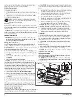
1.  Leaving the flame effect on, remove the log set and wa-

ter tank and lift out the top cover (Figure 3).

2.  View the lamps from a distance in front of the fire and 

observe which lamp needs to be changed.

3.  Turn the unit off, and unplug the unit.
4.  Leave the appliance for 20 minutes to allow the lamps 

to cool down before removing them.

5.  Remove the defective bulb, by gently lifting vertically 

and disengaging the pins from the lamp holder. 

!

 NOTE: 

Replacement light bulbs can be obtained by 

contacting Dimplex Customer Service at 1-888-346-7539.
6.  Carefully insert the two pins of the new bulb into the 

two holes in the lamp holder. Push lamp firmly in place.

7.  Replace the top cover, refill container and log set.

Cleaning

It is recommended that all of the components that contain 

water are cleaned with soap and water on a 

biweekly

 ba-

sis.  A small brush has been included to assist in cleaning 

difficult items/areas, i.e. the transducer.

 CAUTION: 

Do not put plastic components in the dish-

washer.

Filter Cleaning

The air filter can be removed and gently rinsed with water 

to clean and dried on a towel before reinstalling.

!

 NOTE: 

Replace the filter so that the course black filter is 

facing the front of the unit.

Surface Cleaning

Use a warm damp cloth only to clean surfaces of the unit. 

Do not use abrasive cleaners.

!

 NOTE: 

If you need to move the unit ensure that all of 

the components that contain water have been emptied be-

fore relocating.

Figure 3

Top 

Cover

Transducer

Emitter

Wire Slot

Retaining 

Tab

Fan 

Housing

Water Tank

on the unit, or the Off button on the remote control, then 

back on to return to Level 1 - Flame Effect 

Battery Replacement

To replace the battery:
1.  Slide battery cover open on the remote control (Figure 

6).

2.  Install two 1.5 Volt (AAA) battery in the battery holder.
3.  Close the battery cover. 

Battery must be recycled or disposed of properly. 

Check with your Local Authority or Retailer for recy-

cling advice in your area.

Servicing

Except for installation and cleaning described in this manu-

al, an authorized service representative should perform any 

other servicing.

!

NOTE: 

When transporting or storing the unit and cord, 

keep in a dry place, free from excessive vibration and store 

so as to avoid damage.

Summary of Contents for OS2527GB

Page 1: ...h America Limited Dimplex North America Limited 1367 Industrial Road Cambridge ON Canada N3H 4W3 1 888 346 7539 www dimplex com REV PCN DATE 00 15 NOV 16 IMPORTANT SAFETY INFORMATION Always read this manual first before attempting to service this cassette For your safety always comply with all warnings and safety instructions contained in this manual to prevent personal injury or prop erty damage ...

Page 2: ... if not carefully followed will expose the user to the risk of fire serious injury or death Operation 3 Maintenance 4 Exploded Parts Diagram 5 Replacement Parts List 5 Wiring Diagram 6 Remote Control Receiver Replacement 7 Power Board Replacement 7 Switch Replacement 7 Thermostat Replacement 8 Potentiometer Replacement 8 Power Cord Receptacle Replacement 8 Fuse Fuse Assembly Replacement 9 Light As...

Page 3: ...urn on Full heat and Flame effect This will be indicated by two beeps Standby This will be indicated by one beep NOTE Once the mist has been activated the unit will have to be turned Off using either the momentary button OPERATION Figure 1 WARNING This electric firebox must be properly in stalled before it is used NOTE When the unit is used in an environment where background noise is very low it m...

Page 4: ...ch lamp needs to be changed 3 Turn the unit off and unplug the unit 4 Leave the appliance for 20 minutes to allow the lamps to cool down before removing them 5 Remove the defective bulb by gently lifting vertically and disengaging the pins from the lamp holder NOTE Replacement light bulbs can be obtained by contacting Dimplex Customer Service at 1 888 346 7539 6 Carefully insert the two pins of th...

Page 5: ...bly 9600540100RP 11 Fan Filter 8600300100RP 12 Transducer 3800040100RP 13 Power Cord 9600740100RP 14 Receptacle Cord 9600780100RP 15 On Off Switch 9600383500RP 16 3 Position Switch 9600383600RP 17 Transformers 9600690100RP 18 Potentiometer 9600640100RP 19 Thermostat Assembly 9600620100RP 20 Control Knob 9600630200RP 21 Power Board 9600590100RP 22 IR Receiver with Lens 9600600200RP 23 Light Bulbs P...

Page 6: ...om WIRING DIAGRAM LINE IN MOTOR ELEMENT THERMAL CUTOUT PCB ELEMENT THERMOSTAT TRANSFORMER TRANSFORMER LIGHTS LIGHTS POWER BOARD SELECTOR SWITCH POTENTOMETER IR SENSOR TRANSDUCER FAN MOTOR N1 N2 3 4 5 6 NEUTRAL GROUND ...

Page 7: ... secure the cassette assembly to the chassis 4 Lift the cassette assembly out of the unit 5 Remove the 4 screws that secure the front grill to the cassette housing Figure 4 6 Remove the 4 screws around the power board attach ing it to the unit 7 Transfer the wire connectors from the terminals on the original board to the same location on the replacement board Figure 4 Front Grille Transformers Pow...

Page 8: ...ew thermostat and slide the thermostat back into the assembly ensuring that it has clicked into place 10 Re assemble the remainder of the cassette in reverse order from the instructions above POTENTIOMETER REPLACEMENT Tools Required Phillips head screwdriver Flat Head Screwdriver 3 8 10mm Wrench WARNING Disconnect power before attempting any maintenance to reduce the risk of electric shock or dama...

Page 9: ...ewdriver Flat Head Screwdriver WARNING Disconnect power before attempting any maintenance to reduce the risk of electric shock or damage to persons NOTE Ensure that all of the components that contain water have been emptied before performing any maintenance 1 Disconnect and remove the log set from the unit and put it in a safe place 2 From the front of the unit remove the top cover and the water t...

Page 10: ...he unit and put it in a safe place 2 Lay the unit on it s back to access the heater assembly area 3 Remove the 4 screws that secure the assembly to the stove Figure 7 4 Allow the assembly to separate from the stove by gen tly pulling the cord out of the opening in the bottom of the stove 5 Remove the 2 screws on the top of the assembly 2 on the bottom on either side and 2 on either side of the hea...

Page 11: ...t Add 1 8 tsp of table salt to water reservoir to introduce electrolytes only repeat when mist is not being produced correctly Check that the fan is operating correctly Replace fan assembly Ensure that the air filter is clean and dry Cord is located over emitter on transducer Relocate cord so that mist is free to rise off of transducer Defective Transducer Replace Transducer The flame effect is to...

Page 12: ...Fuse Heater is turning off after a couple of minutes of operation Build up of dirt dust in Heater Assembly Ensure that exterior intake louvers and housing cavity are free of dirt dust Defective Heater Assembly Replace Heater Assembly Heater emits an odor Normal Operation Normal operation is when the heater emits an odor for a brief period after the heater is initially turned on The heater is burni...

Reviews: