Dimplex DWF36-PG Service Manual Download Page 7

7

HEATER ASSEMbLY REPLACEMENT

Tools Required:

  Philips head screwdriver

Flat head screwdriver

Needle-nose pliers

  WARNING:

  If the fireplace was operating prior to ser

-

vicing, allow at least 10 minutes for light bulbs and heating 

elements to cool off to avoid accidental burning of skin.

  WARNING:

  Disconnect power before attempting any 

maintenance to reduce the risk of electric shock or damage 

to persons.

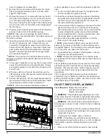
Remove the fireplace from the wall by carefully lifting it 

1. 

upward, releasing it from the flanges of the wall-mount

-

ing bracket. (Figure 3). 
Carefully lay the fireplace down on its front.

2. 

!

 NOTE:

  If necessary, lay a protective barrier between 

the front glass and your work  surface, (i.e. cloth, card-

board, thick plastic) to avoid scratching the glass or your 

work surface.

Remove the left and right side exterior cover panels 

3. 

from the body of the firebox by removing the screw on 

the top flange and two (2) screws on the bottom flange 

on each panel, 6 screws in total. (See Figure 4 for all 

screw locations.)
Remove the six (6) screws from the bottom edge of the 

4. 

back panel.
Remove the twelve (12) screws which secure the bot-

5. 

tom panel to the fireplace:  two (2) on the left and two 

(2) on the right (side flange); three (3) on the left and 

three (3) on the right (corner point of the bottom panel); 

two (2) in the center of the bottom panel (edge closest 

Wall Bracket 

Supports

Wall Bracket

Figure 3

Figure 4

Screw Locations

Exterior Cover Plate Screws

Back Panel Screws

Front Glass Assembly Screws

Bottom Panel Screws

toward the front face).  

Carefully pull the bottom panel away from the fireplace 

6. 

and rest it just in front of the bottom opening.  

!

 NOTE:

  Take care not to damage the wires from the 

power cord, which are still attached to both the bottom 

panel and the interior switches.

Locate the heater assembly and remove the two (2) 

7. 

heater assembly brackets from the back panel.   

(Figure 5)

Carefully remove the heater assembly out through the 

8. 

bottom opening of the fireplace leaving the wires still 

connected.
Remove the two (2) mounting brackets from the original 

9. 

heater assembly, and re-attach them to the new heater 

assembly.
Carefully transfer the wire connections from the original 

10. 

heater assembly onto the new heater assembly. 

!

  NOTE:

  Use a flat head screwdriver to gently pry be

-

tween the end of the connector and the heater assembly to 

release the wires.

Re-attach the mounting brackets to the back panel.

11. 

Re-assemble the remainder of the fireplace in reverse 

12. 

order from the instructions above.

!

 NOTE:

  Be sure that the side flanges on the bottom 

panel are positioned on the interior of the side and back 

panels of the fireplace.  
The air deflector panel located on the interior of the bottom 

panel will need to carefully fit over the heater assembly 

elements.  This may take some careful maneuvering, slid-

ing one side of the bottom panel in place first before the 

Summary of Contents for DWF36-PG

Page 1: ...h America Limited Dimplex North America Limited 1367 Industrial Road Cambridge ON Canada N1R 7G8 1 888 346 7539 www dimplex com REV PCN DATE 00 28 NOV 11 IMPORTANT SAFETY INFORMATION Always read this...

Page 2: ...Procedures and techniques which if not carefully followed will expose the user to the risk of fire serious injury or death Operation 3 Maintenance 4 Exploded Parts Diagram 5 Replacement Parts List 5...

Page 3: ...r area Operation Figure 1 The manual controls for the electric fireplace are located on the right end of the unit A On Off Switch The On Off Switch supplies power to all fireplace functions When the s...

Page 4: ...e removed by dusting lightly with a clean dry cloth To remove fingerprints or other marks the Partially Reflec tive Glass can be cleaned with a damp cloth The Partially Reflective Glass should be comp...

Page 5: ...0259RP Flicker Assembly 3 5902180100RP On Off Switch 4 2800070700RP Power Cord 5 4100190100RP Remote Control Receiver 6 3000820100RP Remote Switchboard 7 3000820300RP Remote Control 8 3000370900RP LED...

Page 6: ...6 www dimplex com Wiring Diagram...

Page 7: ...sest Wall Bracket Supports Wall Bracket Figure 3 Figure 4 Screw Locations Exterior Cover Plate Screws Back Panel Screws Front Glass Assembly Screws Bottom Panel Screws toward the front face Carefully...

Page 8: ...nels on the left and right sides These hold the interior Partially Reflective Glass brackets in place and may cause the Partially Reflective Glass to fall and break Lift the glass assembly off the bod...

Page 9: ...Note Be sure that the flanges on the bottom panel are positioned on the interior of the side and back panels of the fireplace The air deflector panel located on the interior of the bottom panel will...

Page 10: ...to the lower electrical compartment In the lower electrical compartment reconnect the LED 19 light strip to the wires on the LED driver board using the 2 orange wire nut connectors Be sure to follow t...

Page 11: ...lid ing one side of the bottom panel in place first before the second side The fit is tight and a flat instrument such as a flat head screwdriver may be helpful to guide the second side when pushing t...

Page 12: ...left and three 3 on the right corner peak of the bottom panel two 2 in the center of the bottom panel edge toward the front face Carefully pull the bottom panel away from the fireplace 7 and rest it...

Page 13: ...uch Appearance Fireplace does not turn on in Manual Mode Improper operation Refer to Operation Section No incoming power from the electrical wall socket Check Fuse Breaker Panel Defective On Off Switc...

Page 14: ...r operation Defective heater assembly Replace heater assembly Heater fan turns on but heater lacks heat Improper operation Refer to Operation Section Loose wiring Trace wiring in unit Defective heater...

Reviews: