Dimplex DS5629 Service Manual Download Page 9

9

Loosen the 2 retainers on the inner sides of the unit by 

2. 

turning counter clockwise.
Remove 4 screws that secure the top on the rear of the 

3. 

unit.
Lift the top off of the unit.  Carefully remove the mirror 

4. 

and store in a safe place to prevent damage.
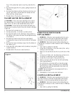
SWITCHES

Locate the switches on the back wall of the unit.

5. 

Remove wiring connections from the switches noting 

6. 

their original locations.
Squeeze the tabs on the top and bottom of the switch 

7. 

and push out through the back of the unit.

THERMOSTAT

Locate the thermostat on the back wall of the unit.

8. 

Remove the wiring from the thermostat noting their 

9. 

original locations.
Remove the thermostat knob and 2 mounting screws.

10. 

Connect all of the wiring connections in their original 

11. 

locations.
Reassemble in the reverse order as above.

12. 

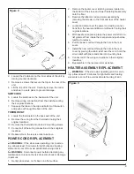
POWER CORD REPLACEMENT

  WARNINg:

  If the stove was operating prior to servic-

ing, allow at least 10 minutes for light bulbs and heating 

elements to cool off to avoid accidental burning of skin.

  WARNINg:

  Disconnect power before attempting any 

maintenance to reduce the risk of electric shock or damage 

to persons.

Gently place stove on it’s back on a flat surface.

1. 

Remove the heater cover retaining screws located on 

2. 

the bottom of the stove and lower heater/light assembly 

onto the floor.
Remove the reflector rod and motor assembly by 

3. 

removing the screws on the front and rear of the heater 

cover.
Locate and disconnect the power cord wiring connec-

4. 

tions from the heater and Main on/off switch noting their 

original locations.
With needle nose pliers, grasp the power cord strain re-

5. 

lief grommet from inside the rear panel and push while 

twisting to remove.
Pull the power cord out through the hole in the rear 

6. 

cover.
Install the new cord set through the hole in the rear 

7. 

cover by placing the strain relief over the cord, hold the 

strain relief with pliers and slide into mounting hole.
Connect all of the wiring connections in their original 

8. 

locations.
Reassemble in the reverse order as above.

9. 

HEATER ASSEMBLY REPLACEMENT

  WARNINg:

  If the stove was operating prior to servic-

ing, allow at least 10 minutes for light bulbs and heating 

elements to cool off to avoid accidental burning of skin.


Figure 8


Figure 9

Summary of Contents for DS5629

Page 1: ...North America Limited Dimplex North America Limited 1367 Industrial Road Cambridge ON Canada N1R 7G8 1 888 346 7539 www dimplex com REV PCN DATE 01 9 Sep 11 IMPORTANT SAFETY INFORMATION Always read t...

Page 2: ...d techniques which if not carefully followed will expose the user to the risk of fire serious injury or death OPERATION 3 Maintenance 4 Exploded Parts Diagram 5 Wiring Diagram 6 LIGHT BULB REPLACEMENT...

Page 3: ...your Local Authority or Retailer for recycling advice in your area OPERATION To access the controls go to the back of the Stove Figure 1 A Three position ON OFF switch The switch has two ON positions...

Page 4: ...lb Replacement Open door by pulling the handle 1 Remove the screw from the logset located in the center 2 of the emberbed and remove the logset from the unit Locate and examine the bulbs to determine...

Page 5: ...lame Rod 7 5900080600RP Strain Relief Bushing 8 8500000400RP Log Set 9 0438780100RP Lampholder 10 4200121000RP Cord Set 11 4100040900RP Terminal Block 12 4000070100RP Capacitor 13 2300030100RP Mirror...

Page 6: ...6 www dimplex com Wiring Diagram...

Page 7: ...ket down 3 Locate and remove the light bulb 4 Insert new bulb 5 Bend light retainer bracket back into its original posi 6 tion Close the door 7 LOWER LIGHT BULB REPLACEMENT LOWER LIGHT BULB REQUIREMEN...

Page 8: ...d REPLACEMENT WARNING If the stove was operating prior to servic ing allow at least 10 minutes for light bulbs and heating elements to cool off to avoid accidental burning of skin WARNING Disconnect p...

Page 9: ...wer before attempting any maintenance to reduce the risk of electric shock or damage to persons Gently place stove on it s back on a flat surface 1 Remove the heater cover retaining screws located on...

Page 10: ...ining screws located on 2 the bottom of the stove and lower heater light assembly onto the floor Remove the reflector rod and motor assembly by 3 removing the screws on the front and rear of the heate...

Page 11: ...itch Loose wiring Check wiring connections Stove does not turn on with remote Improper operation Refer to Operation Section Remote control not initialized to stove Initialize the remote control Defect...

Page 12: ...ce thermostat Loose wiring Trace wiring in unit Defective heater assembly Replace heater assembly Heating element is glowing red Normal Operation Small glowing sections of the element are considered n...

Reviews: